Tag Archives: motor gearbox

China Customized Walking Speed Electric Motor Driving Wheelbarrow Machinery Rear Wheel Axles with 24V500w BLDC Motor and Split Gearbox axle shaft

Use: Trailer Elements
Components: Trailer Axles
OE NO.: MK
Max Payload: 5
One particular-Cease Support

Packaging & S750 48V 10KW H2o Sea Sporting activities RC Water-resistant Surf Board Thruster DC Brushless Rubber Boat Motor Shipping and delivery
one) We acknowledge ship your cargo by DHL, FEDEX, UPS, TNT,EMS Categorical Courier, or By Air,By Ship,other kind of shipping and delivery according to your requirements2) To Avoid any errors for supply,prior to cargo,kindly advise the element details about your Company Identify/Company Address/Postal Code/Phone&Mobile Variety/Email/Tax Amount/Get in touch with Man or woman Name,and so forth.3) We take wonderful treatment in packaging every single merchandise to make certain protected shipment to you.
Certifications
Company Information

Firm Profile
We,Michael Equipment,as a sub-business of CZPT Investment Group, is a proffessional spare elements supplier to all kinds of vehicles and equipment because 1990.
Once more,we are the leader of axle manufactor in China, 10 Inch 500W 60V Potent Dc Brushless Electric powered Wheel Hub Motor and maintain long-phrase cooperation with plenty of motor vehicle spare parts factories,we can give you one-cease obtain provider to total motor vehicle chassis spare areas,
” Reputable-High quality, Resonable-Value, Quick-Shipping ” is our services idea, after far more than thirty a long time improvements,we are the main supplier to car industries & reffitting factories at home and abroard,
Welcome to pay a visit to our factory for organization together.

FAQQ1. What is actually the MOQ? Can I acquire 1 sample for tests?A: Usually MOQ is 5-50 Piece to various components . We accept sample or trial purchase.Q2. Can you provide Free SAMPLE?A: Sorry, our sample plan is that you may pay for the sample and shipping and delivery cost 1st, and we will refund it when you purchase them in mass amount not considerably less than a hundred-1000pcs in accordance to MQO.Q3. What’s your supply time and shipping and delivery way?A: About 10-15days for sample supply time (By Express). twenty five-30 times for mass production or it is dependent on your buy quantity (By Sea or Air as you required)Q4. What provider can we provide?A: Recognized Shipping and delivery Conditions: FOB,CFR,CIF, SXIHU (WEST LAKE) DIS.NG MOT 24V Inrunner Underwater Stern Thruster DC Motor for RC Paddle Board Marine Truster EXW,CIP,DDP,DAF Accepted Payment Currency:USD,EUR Recognized Payment Type: T/T,L/C,D/P D/A,Credit rating Card,PayPal,Cash Language Spoken:English,ChineseQ5. How to get the suited elements for my autos, what must I do?A: You should send your car specifications in details,it is better to ship the parts picture and drawing or samples for our examining.

Q6. How can we promise good quality?A: Always a pre-manufacturing sample prior to mass generation
Always 100% examination to last Inspection before shipment.

What Is an Axle?

An axle is the central shaft of a vehicle that rotates a wheel or gear. It may be fixed to the wheels or to the vehicle itself, and can rotate with the wheels and gears. It may include bearings and mounting points. If the axle is fixed to the vehicle, it may have a steering or drive shaft attached.

Rear axle

The rear axle is a crucial part of your vehicle. If it fails to function correctly, it can cause major issues when driving at high speeds. This assembly can be a complicated component, and it is crucial that you find a mechanic who knows how to fix it. Rear axles require periodic gear oil replacement and bearing adjustments.
The rear axle is the final leg of the drivetrain, transferring rotational power from the driveshaft to the rear wheels. While the design of the rear axle varies between vehicles, all axles are designed to follow similar principles. Rear axles may have a single drive shaft or two. The drive shafts are mounted at either end of the axle.
The rear axle ratio is important because it affects how much fuel the truck uses. The lower the ratio, the more fuel-efficient the vehicle is. Higher numbers, like 4:10, are better for towing, but they will decrease fuel economy. When choosing a rear axle ratio, be sure to consider how much weight you’ll be hauling.
The rear axle is the most complicated part of the vehicle. It has many components and may not be easily visible. However, a properly functioning rear axle is essential for maximizing safety and performance. If you have a problem, you should contact a professional for a quick and easy fix. Even minor issues can make a significant difference in how your car or truck functions. A professional will ensure that your vehicle’s rear axle will be up to OEM standards.
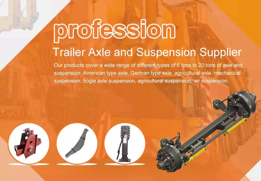
Axles

Semi-floating axle

A semi-floating axle is the next step up from a stub axle. Semi-floating axles have a bearing that supports the shaft, which then floats inside the axle casing. These axles are best suited for midsize trucks. They are also lighter than full-floating axles and can be manufactured at a lower cost.
This design is most commonly found on rear-wheel-drive passenger cars and lighter trucks. The semi-floating design also allows for a wider diameter axle shaft, and it can increase axle capacity by increasing the diameter of the axle shaft. It also has a wider offset to accommodate larger tires. It can accommodate any offset, although this is usually only useful in off-road environments.
Semi-floating axles are often made with a tapered end. This helps keep the axel from twisting while providing traction. The rear hub of a semi-floating axle is usually connected to the axel via a big, strong nut. This nut also provides friction on the axel shaft.
A full-floating axle is common in 3/4-ton and 1/2-ton trucks. It is important to note, however, that almost all factory full-floating rear ends use eight-lug wheels. However, this rule is not strictly enforced and some companies, like Czpt, specialize in semi-floating axles and custom axles.
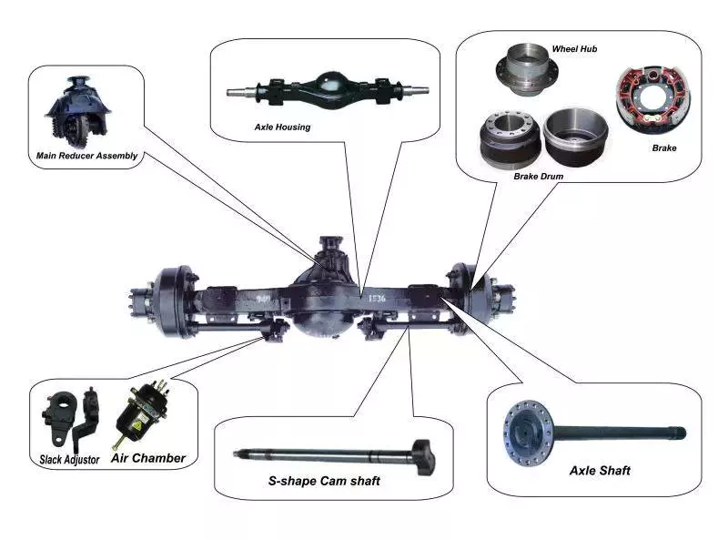
Axles

Drive shaft

A drive shaft is an important part of your vehicle’s drivetrain, which helps to transfer torque from the transmission to the drive wheels. You’ll need to know how it functions in order to properly maintain your car. Fortunately, there are a variety of different parts you can use to upgrade your drive shaft.
In order to improve the performance of your vehicle’s drivetrain, you can replace your existing drive shaft with an upgraded one. These are available in various lengths, so that you can find the right length and fit for your vehicle. Some shafts can even be customized to fit the exact length of your axle.
Generally, short axle shafts are made of solid steel. The longer ones are made of aluminum or carbon fiber. To ensure a smooth and safe ride, they are dynamically balanced to eliminate vibrations. Some models are fitted with giubo joints and universal joints to absorb shock. You can also add flex discs to improve your suspension and dampen the bucking sensation of a drive shaft.
You can tell if your drive shaft needs replacement if you hear a clicking noise while driving. This noise is often audible when the vehicle is turning sharply. You should take your vehicle to a mechanic as soon as you hear this noise, or it could lead to a costly repair. In addition to a clicking noise, your car may also be exhibiting a shuddering or vibrating sensation. If you’re experiencing any of these symptoms, you should take your car in for a checkup by an ASE certified technician. If you ignore these warnings, your car’s drive shaft could separate, causing you a lot of damage.
The drive shaft is attached to the axle flange by a drive shaft bolt. This is an important part of the drivetrain because it’s the only point where the drive shaft will connect to the axle. If the bolt is too long, it could be vulnerable to damage if the washers don’t fit tightly. The drive shaft socket yoke can also be easily damaged when you loosen the bolt.
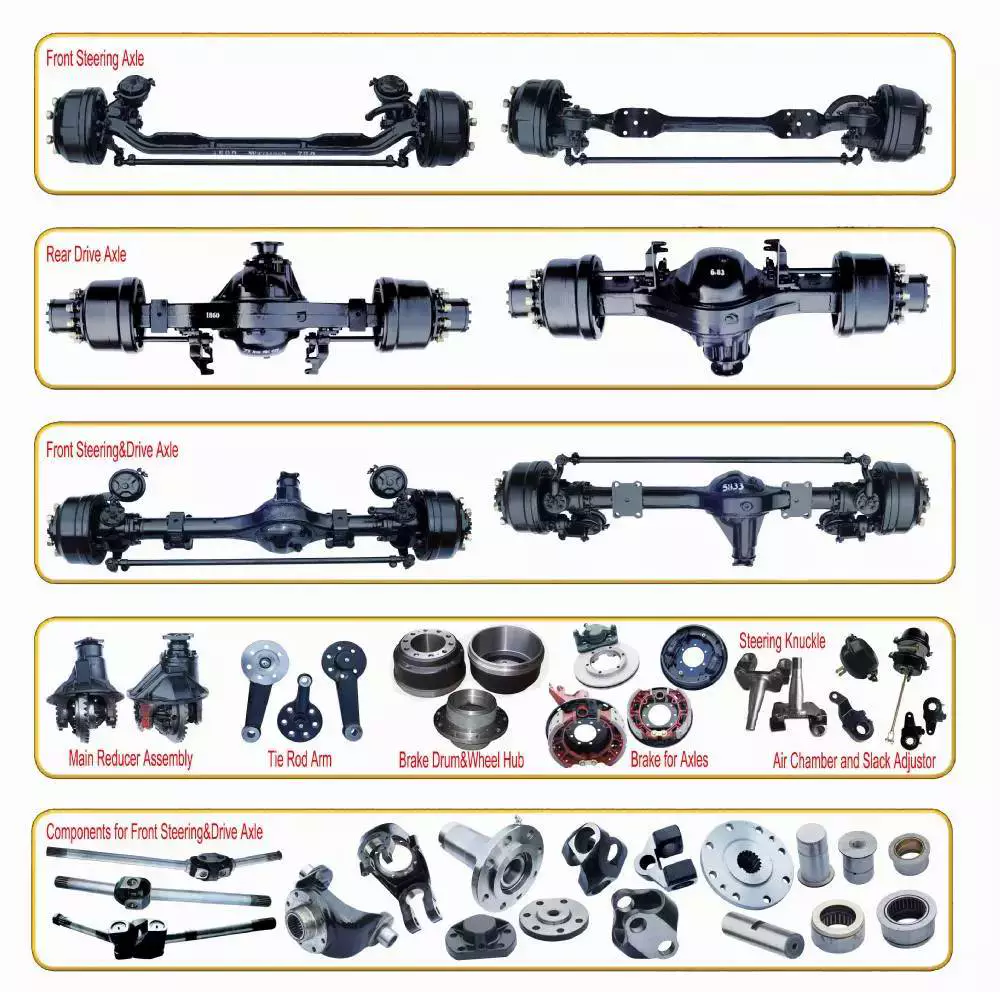
Axles

U-joint

When you replace a u-joint on an axle, you need to take a few things into consideration. One of these considerations is the type of grease you’re going to use. Some of these greases are better than others, and you should always check for a quality grease before you install a new one. A good grease can help to reduce the friction and improve the temperature resistance of the part.
It’s also important to check the u-joint itself. This is the joint between the axle shaft and the wheel. If it’s not functioning properly, it could cause further problems. You should inspect the u-joint every time you change the oil in your vehicle. You can test its lubrication by pressing on the tire with a pry bar or axle stands. You can also try turning the steering wheel fully to test if the joint is loose.
A u-joint failure can leave your car inoperable, which can make driving a risky proposition. If the drive shaft loosens and falls to the ground, you could lose control of your car and risk being stranded. In some severe cases, the front of the driveshaft can even drop to the ground and lift the rear of the car, pushing the car sideways. It’s vital to check u-joints regularly, as failure of the u-joint can cause costly and frustrating car repairs.
When you notice a bad universal joint, you should consider getting it replaced immediately. The most common symptom of a bad u-joint is a clunking sound during acceleration and deceleration. You may also hear vibrations when the u-joint becomes worn and you drive the car. If you notice these symptoms, contact a qualified technician to perform a proper diagnosis.
China Customized Walking Speed Electric Motor Driving Wheelbarrow Machinery Rear Wheel Axles with 24V500w BLDC Motor and Split Gearbox     axle shaftChina Customized Walking Speed Electric Motor Driving Wheelbarrow Machinery Rear Wheel Axles with 24V500w BLDC Motor and Split Gearbox     axle shaft
editor by czh 2023-03-09

China Best Sales 32mm Planet Gearbox with Electronic DC Brush / Stepper / Brushless Drive Motor Encoder Controller near me shop

Product Description

We are a factory specialized in metal parts hardware & metal gearbox geared motor through powder metallurgy process .We services with ODM/OEM gearbox design and development , gearmotors manufacture.
A planetary gear set is made up of 3 types of gears , a sun gear , planet gears and a ring gear . The sun gear at high speed is located at the center of the gears , and transmits torque to the planet gears which are typically mounted on the moveable carrier .The planet gears around the central axis rotation ,mesh with the sun gear and an outer ring gear . As all the planet carriers turns , it delivers low-speed, high-torque output .
Low-Cost, High-Efficiency Planetary Gear Systems
Planetary gearboxes are especially efficient, they are suitable for continuous, intermittent and alternating operation as well as for clockwise and anticlockwise rotation. Their use results in an increased performance of the entire drive train since the choice of the right gearbox allows for a smaller motor and thereby increases the economic efficiency of the entire drive train.
planetary gearbox with optimized helical gearset teeth was developed for highly demanding applications. These gearbox is perfect for applications ranging from basic machinedesign to printing, packaging, and robotics.
Features:
The highest dynamics in multiple axis systems
Unrivaled price-performance ratio
Low heat generation at highest speeds
For any mounting position
Lifetime lubrication for maintenance-free operation
Precise gearing

Description:
Product Name : 16mm planet gearbox with DC brushed motors  high torque geared motor / Speed reducer / steel gearbox
Gearbox Type: Planetary
Material: Steel 
16mm

No-load Speed: 4-1,373 rpm

Rated Load Speed: 3-1,125 rpm
No-load Current: 85-110 mA

Rated Load Current: 130-150 mA

20mm

No-load Speed: 7-1,636 rpm

Rated Load Speed: 7-1,420 rpm
No-load Current: 70-90 mA

Rated Load Current: 125-130 mA

36mm

No-load Speed: 3-1,375 rpm

Rated Load Speed: 3-1,280 rpm
 

No-load Current: 300-325 mA

Rated Load Current: 1,679-1,684 mA

Gear Ratio : 5:1 , 10:1 , 20:1 , 25:1 , 30:1 , 40:1 , 50:1 , 60:1 ,70:1…100:1…  optional
Gearbox diameter : 6mm , 8mm , 12mm , 16mm , 22mm , 24mm ,28mm, 32mm ,36mm, 38mm , 42mm ……
12-24V available .

Planetary Gearbox advantages:

  • Easy and functional flange, foot, or shaft-mounting design
  • High torque transmitted
  • Extended range of transmission ratios and output speeds available

Application:
monitor,automatic vending machine,automatic cruise control,door lock actuator, retractable rearview mirror, meters, optic axis control device, head light beam level adjuster,printers,conditioning damper actuator,Car tail gate electric putter,tooth brush,vibrator, sanitary ware,coffee machine,Sweeping robot,etc.

Welcome send us drawings for OEM service .


Workshop

Different parts of the drive shaft

The driveshaft is the flexible rod that transmits torque between the transmission and the differential. The term drive shaft may also refer to a cardan shaft, a transmission shaft or a propeller shaft. Parts of the drive shaft are varied and include:
The driveshaft is a flexible rod that transmits torque from the transmission to the differential

When the driveshaft in your car starts to fail, you should seek professional help as soon as possible to fix the problem. A damaged driveshaft can often be heard. This noise sounds like “tak tak” and is usually more pronounced during sharp turns. However, if you can’t hear the noise while driving, you can check the condition of the car yourself.
The drive shaft is an important part of the automobile transmission system. It transfers torque from the transmission to the differential, which then transfers it to the wheels. The system is complex, but still critical to the proper functioning of the car. It is the flexible rod that connects all other parts of the drivetrain. The driveshaft is the most important part of the drivetrain, and understanding its function will make it easier for you to properly maintain your car.
Driveshafts are used in different vehicles, including front-wheel drive, four-wheel drive, and front-engine rear-wheel drive. Drive shafts are also used in motorcycles, locomotives and ships. Common front-engine, rear-wheel drive vehicle configurations are shown below. The type of tube used depends on the size, speed and strength of the drive shaft.
The output shaft is also supported by the output link, which has 2 identical supports. The upper part of the drive module supports a large tapered roller bearing, while the opposite flange end is supported by a parallel roller bearing. This ensures that the torque transfer between the differentials is efficient. If you want to learn more about car differentials, read this article.
air-compressor

It is also known as cardan shaft, propeller shaft or drive shaft

A propshaft or propshaft is a mechanical component that transmits rotation or torque from an engine or transmission to the front or rear wheels of a vehicle. Because the axes are not directly connected to each other, it must allow relative motion. Because of its role in propelling the vehicle, it is important to understand the components of the driveshaft. Here are some common types.
Isokinetic Joint: This type of joint guarantees that the output speed is the same as the input speed. To achieve this, it must be mounted back-to-back on a plane that bisects the drive angle. Then mount the 2 gimbal joints back-to-back and adjust their relative positions so that the velocity changes at 1 joint are offset by the other joint.
Driveshaft: The driveshaft is the transverse shaft that transmits power to the front wheels. Driveshaft: The driveshaft connects the rear differential to the transmission. The shaft is part of a drive shaft assembly that includes a drive shaft, a slip joint, and a universal joint. This shaft provides rotational torque to the drive shaft.
Dual Cardan Joints: This type of driveshaft uses 2 cardan joints mounted back-to-back. The center yoke replaces the intermediate shaft. For the duplex universal joint to work properly, the angle between the input shaft and the output shaft must be equal. Once aligned, the 2 axes will operate as CV joints. An improved version of the dual gimbal is the Thompson coupling, which offers slightly more efficiency at the cost of added complexity.
air-compressor

It transmits torque at different angles between driveline components

A vehicle’s driveline consists of various components that transmit power from the engine to the wheels. This includes axles, propshafts, CV joints and differentials. Together, these components transmit torque at different angles between driveline components. A car’s powertrain can only function properly if all its components work in harmony. Without these components, power from the engine would stop at the transmission, which is not the case with a car.
The CV driveshaft design provides smoother operation at higher operating angles and extends differential and transfer case life. The assembly’s central pivot point intersects the joint angle and transmits smooth rotational power and surface speed through the drivetrain. In some cases, the C.V. “U” connector. Drive shafts are not the best choice because the joint angles of the “U” joints are often substantially unequal and can cause torsional vibration.
Driveshafts also have different names, including driveshafts. A car’s driveshaft transfers torque from the transmission to the differential, which is then distributed to other driveline components. A power take-off (PTO) shaft is similar to a prop shaft. They transmit mechanical power to connected components. They are critical to the performance of any car. If any of these components are damaged, the entire drivetrain will not function properly.
A car’s powertrain can be complex and difficult to maintain. Adding vibration to the drivetrain can cause premature wear and shorten overall life. This driveshaft tip focuses on driveshaft assembly, operation, and maintenance, and how to troubleshoot any problems that may arise. Adding proper solutions to pain points can extend the life of the driveshaft. If you’re in the market for a new or used car, be sure to read this article.

it consists of several parts

“It consists of several parts” is 1 of 7 small prints. This word consists of 10 letters and is 1 of the hardest words to say. However, it can be explained simply by comparing it to a cow’s kidney. The cocoa bean has several parts, and the inside of the cocoa bean before bursting has distinct lines. This article will discuss the different parts of the cocoa bean and provide a fun way to learn more about the word.
air-compressor

Replacement is expensive

Replacing a car’s driveshaft can be an expensive affair, and it’s not the only part that needs servicing. A damaged drive shaft can also cause other problems. This is why getting estimates from different repair shops is essential. Often, a simple repair is cheaper than replacing the entire unit. Listed below are some tips for saving money when replacing a driveshaft. Listed below are some of the costs associated with repairs:
First, learn how to determine if your vehicle needs a driveshaft replacement. Damaged driveshaft components can cause intermittent or lack of power. Additionally, improperly installed or assembled driveshaft components can cause problems with the daily operation of the car. Whenever you suspect that your car needs a driveshaft repair, seek professional advice. A professional mechanic will have the knowledge and experience needed to properly solve the problem.
Second, know which parts need servicing. Check the u-joint bushing. They should be free of crumbs and not cracked. Also, check the center support bearing. If this part is damaged, the entire drive shaft needs to be replaced. Finally, know which parts to replace. The maintenance cost of the drive shaft is significantly lower than the maintenance cost. Finally, determine if the repaired driveshaft is suitable for your vehicle.
If you suspect your driveshaft needs service, make an appointment with a repair shop as soon as possible. If you are experiencing vibration and rough riding, driveshaft repairs may be the best way to prevent costly repairs in the future. Also, if your car is experiencing unusual noise and vibration, a driveshaft repair may be a quick and easy solution. If you don’t know how to diagnose a problem with your car, you can take it to a mechanic for an appointment and a quote.

China Best Sales 32mm Planet Gearbox with Electronic DC Brush / Stepper / Brushless Drive Motor Encoder Controller   near me shop China Best Sales 32mm Planet Gearbox with Electronic DC Brush / Stepper / Brushless Drive Motor Encoder Controller   near me shop

China wholesaler Solar Sun Panel Automatic Tracking Gear Reduction Nmrv Worm Gearbox Tracker System Slewing Drive DC Geared Stepper Electrical Motor with Free Design Custom

Product Description

Solar Sun Panel Automatic Tracking Gear Reduction NMRV Worm Gearbox Tracker System Slewing Drive DC Geared Stepper Electrical Motor

Product Description

Solar tracker motor is also named solar tracking system controlling motor, it is used for solar power generation equipment. The motor has a very low speed, generally, 1~3 rpm which accords with the feature of a DC planetary gear motor. Because the reduction ratio of the planetary gearbox can be very large to achieve very low speed.
The following DC planetary gear motors, stepping planetary gear motors can resist and work well in bad weather conditions with their safe and reliable use, and meet the demands of small and medium automatic tracking systems.

Detailed Photos


Typical applications


Product Parameters


No

Model

A52R50D24

1

Drive series

4

2

Gearbox Ratio

860.6:1

3

Rated output torque

400 Nm

4

Max torque

320 Nm

5

Rated output speed

1 rpm

6

Rated current (A)

5

7

Rated voltage(v)

24

8

Noise (dB)

≤60

9

Working temperature(ºC)

-40~80

10

IP Grade

IP65

Our Advantages


Company Profile


FAQ

Q: Can you make the gear motor with customization?
A: Yes, we can customize per your request, like power, voltage, speed, shaft size, wires, connectors, IP grade, etc.

Q: Do you provide samples?
A: Yes. The sample is available for testing.

Q: What is your MOQ?
A: It is 10pcs for the beginning of our business.

Q: What’s your lead time?
A: Standard products need 5-30days, a bit longer for customized products.

Q: Do you provide technical support?
A: Yes. Our company have design and development team, we can provide technical support if you
need.

Q: How to ship to us?
A: It is available by air, or by sea, or by train.

Q: How to pay the money?
A: T/T and L/C are preferred, with a different currency, including USD, EUR, RMB, etc.

Q: How can I know the product is suitable for me?
A: >1ST confirm drawing and specification >2nd test sample >3rd start mass production.

Q: Can I come to your company to visit?
A: Yes, you are welcome to visit us at any time.

Q: How shall we contact you?
A: You can send an inquiry directly, and we will respond within 24 hours.

Calculating the Deflection of a Worm Shaft

In this article, we’ll discuss how to calculate the deflection of a worm gear’s worm shaft. We’ll also discuss the characteristics of a worm gear, including its tooth forces. And we’ll cover the important characteristics of a worm gear. Read on to learn more! Here are some things to consider before purchasing a worm gear. We hope you enjoy learning! After reading this article, you’ll be well-equipped to choose a worm gear to match your needs.
worm shaft

Calculation of worm shaft deflection

The main goal of the calculations is to determine the deflection of a worm. Worms are used to turn gears and mechanical devices. This type of transmission uses a worm. The worm diameter and the number of teeth are inputted into the calculation gradually. Then, a table with proper solutions is shown on the screen. After completing the table, you can then move on to the main calculation. You can change the strength parameters as well.
The maximum worm shaft deflection is calculated using the finite element method (FEM). The model has many parameters, including the size of the elements and boundary conditions. The results from these simulations are compared to the corresponding analytical values to calculate the maximum deflection. The result is a table that displays the maximum worm shaft deflection. The tables can be downloaded below. You can also find more information about the different deflection formulas and their applications.
The calculation method used by DIN EN 10084 is based on the hardened cemented worm of 16MnCr5. Then, you can use DIN EN 10084 (CuSn12Ni2-C-GZ) and DIN EN 1982 (CuAl10Fe5Ne5-C-GZ). Then, you can enter the worm face width, either manually or using the auto-suggest option.
Common methods for the calculation of worm shaft deflection provide a good approximation of deflection but do not account for geometric modifications on the worm. While Norgauer’s 2021 approach addresses these issues, it fails to account for the helical winding of the worm teeth and overestimates the stiffening effect of gearing. More sophisticated approaches are required for the efficient design of thin worm shafts.
Worm gears have a low noise and vibration compared to other types of mechanical devices. However, worm gears are often limited by the amount of wear that occurs on the softer worm wheel. Worm shaft deflection is a significant influencing factor for noise and wear. The calculation method for worm gear deflection is available in ISO/TR 14521, DIN 3996, and AGMA 6022.
The worm gear can be designed with a precise transmission ratio. The calculation involves dividing the transmission ratio between more stages in a gearbox. Power transmission input parameters affect the gearing properties, as well as the material of the worm/gear. To achieve a better efficiency, the worm/gear material should match the conditions that are to be experienced. The worm gear can be a self-locking transmission.
The worm gearbox contains several machine elements. The main contributors to the total power loss are the axial loads and bearing losses on the worm shaft. Hence, different bearing configurations are studied. One type includes locating/non-locating bearing arrangements. The other is tapered roller bearings. The worm gear drives are considered when locating versus non-locating bearings. The analysis of worm gear drives is also an investigation of the X-arrangement and four-point contact bearings.
worm shaft

Influence of tooth forces on bending stiffness of a worm gear

The bending stiffness of a worm gear is dependent on tooth forces. Tooth forces increase as the power density increases, but this also leads to increased worm shaft deflection. The resulting deflection can affect efficiency, wear load capacity, and NVH behavior. Continuous improvements in bronze materials, lubricants, and manufacturing quality have enabled worm gear manufacturers to produce increasingly high power densities.
Standardized calculation methods take into account the supporting effect of the toothing on the worm shaft. However, overhung worm gears are not included in the calculation. In addition, the toothing area is not taken into account unless the shaft is designed next to the worm gear. Similarly, the root diameter is treated as the equivalent bending diameter, but this ignores the supporting effect of the worm toothing.
A generalized formula is provided to estimate the STE contribution to vibratory excitation. The results are applicable to any gear with a meshing pattern. It is recommended that engineers test different meshing methods to obtain more accurate results. One way to test tooth-meshing surfaces is to use a finite element stress and mesh subprogram. This software will measure tooth-bending stresses under dynamic loads.
The effect of tooth-brushing and lubricant on bending stiffness can be achieved by increasing the pressure angle of the worm pair. This can reduce tooth bending stresses in the worm gear. A further method is to add a load-loaded tooth-contact analysis (CCTA). This is also used to analyze mismatched ZC1 worm drive. The results obtained with the technique have been widely applied to various types of gearing.
In this study, we found that the ring gear’s bending stiffness is highly influenced by the teeth. The chamfered root of the ring gear is larger than the slot width. Thus, the ring gear’s bending stiffness varies with its tooth width, which increases with the ring wall thickness. Furthermore, a variation in the ring wall thickness of the worm gear causes a greater deviation from the design specification.
To understand the impact of the teeth on the bending stiffness of a worm gear, it is important to know the root shape. Involute teeth are susceptible to bending stress and can break under extreme conditions. A tooth-breakage analysis can control this by determining the root shape and the bending stiffness. The optimization of the root shape directly on the final gear minimizes the bending stress in the involute teeth.
The influence of tooth forces on the bending stiffness of a worm gear was investigated using the CZPT Spiral Bevel Gear Test Facility. In this study, multiple teeth of a spiral bevel pinion were instrumented with strain gages and tested at speeds ranging from static to 14400 RPM. The tests were performed with power levels as high as 540 kW. The results obtained were compared with the analysis of a three-dimensional finite element model.
worm shaft

Characteristics of worm gears

Worm gears are unique types of gears. They feature a variety of characteristics and applications. This article will examine the characteristics and benefits of worm gears. Then, we’ll examine the common applications of worm gears. Let’s take a look! Before we dive in to worm gears, let’s review their capabilities. Hopefully, you’ll see how versatile these gears are.
A worm gear can achieve massive reduction ratios with little effort. By adding circumference to the wheel, the worm can greatly increase its torque and decrease its speed. Conventional gearsets require multiple reductions to achieve the same reduction ratio. Worm gears have fewer moving parts, so there are fewer places for failure. However, they can’t reverse the direction of power. This is because the friction between the worm and wheel makes it impossible to move the worm backwards.
Worm gears are widely used in elevators, hoists, and lifts. They are particularly useful in applications where stopping speed is critical. They can be incorporated with smaller brakes to ensure safety, but shouldn’t be relied upon as a primary braking system. Generally, they are self-locking, so they are a good choice for many applications. They also have many benefits, including increased efficiency and safety.
Worm gears are designed to achieve a specific reduction ratio. They are typically arranged between the input and output shafts of a motor and a load. The 2 shafts are often positioned at an angle that ensures proper alignment. Worm gear gears have a center spacing of a frame size. The center spacing of the gear and worm shaft determines the axial pitch. For instance, if the gearsets are set at a radial distance, a smaller outer diameter is necessary.
Worm gears’ sliding contact reduces efficiency. But it also ensures quiet operation. The sliding action limits the efficiency of worm gears to 30% to 50%. A few techniques are introduced herein to minimize friction and to produce good entrance and exit gaps. You’ll soon see why they’re such a versatile choice for your needs! So, if you’re considering purchasing a worm gear, make sure you read this article to learn more about its characteristics!
An embodiment of a worm gear is described in FIGS. 19 and 20. An alternate embodiment of the system uses a single motor and a single worm 153. The worm 153 turns a gear which drives an arm 152. The arm 152, in turn, moves the lens/mirr assembly 10 by varying the elevation angle. The motor control unit 114 then tracks the elevation angle of the lens/mirr assembly 10 in relation to the reference position.
The worm wheel and worm are both made of metal. However, the brass worm and wheel are made of brass, which is a yellow metal. Their lubricant selections are more flexible, but they’re limited by additive restrictions due to their yellow metal. Plastic on metal worm gears are generally found in light load applications. The lubricant used depends on the type of plastic, as many types of plastics react to hydrocarbons found in regular lubricant. For this reason, you need a non-reactive lubricant.

China wholesaler Solar Sun Panel Automatic Tracking Gear Reduction Nmrv Worm Gearbox Tracker System Slewing Drive DC Geared Stepper Electrical Motor   with Free Design CustomChina wholesaler Solar Sun Panel Automatic Tracking Gear Reduction Nmrv Worm Gearbox Tracker System Slewing Drive DC Geared Stepper Electrical Motor   with Free Design Custom