Tag Archives: gear

China Custom Available CZPT in Bulk Landing Gear 13ton Trailer Axle with ISO/Ts16949 axle bolt

Product Description

13ton Trailer Axle Rear Axle for India Market   
 

Company introduction:

ZheJiang CZPT Co.,Ltd is 1 of the major manufacturers specializing in the production of trailer axles.

Our company has high technological background, sophisticated manufacturing technology, advances detection means, perfect quality assurance system. It is a specialized manufacturer integrating scientific research, design, production and sales.

The production of “FUSAI” trailer axles passed the national authoritative department detection. The fatigue life is up to 1,500,000 times without damage-more than 3 times above the national standard, which is in the leading domestic level, and reach or exceed the international standards. Our products are popular not only in domestic markets, but all over the world. Since the products are designed and optimized by computer, they have reasonable structure, good braking performance, high strength and rigidity, strong bearing capacity, long service life, good service, trusted by the users.   

“FUSAI” brand Fuwa style trailer axle
1.CZPT spindle design which is the widely used in the industry with proven performance
2.Low-alloy machined spindles, friction welded seamlessly, and overall heat treating process
3.Axle stubs and brake hubs are all CZPT forging, ensure they are more powerful and better steady
4.Special clone-shape design on the axle-shoulders, lessening stress concentration and enhancing anti-fatigue performance
5.Unique design on axle stubs (with a precise declination angel at both ends) to minimize tire wear
6.National and industry standard compliant set components
7.National Automobile Monitor and Inspection Center certified axle shaft that undergoes over 1.2 million times of Fatigue testing and built to meet or exceed national industry standards.

Specifications:

Axle Type Bearings Max.
Capacity
(T)
Brake
(mm)
Track
(mm)
 
Center
Distance
Of
Brake
Chamber
(mm)
Axle
Tube
(mm)
Stud
 
PCD
(mm)
Hole
Diameter
(mm)
 
Total
Length
(mm)
Weight
(kg)
FS-
2001
HM212049/10
HM218248/10
11 420*180 1850 410 Φ127*16 10*M22*1.5ISO 285.75 221 2185 363
FS-
2002
HM212049/10
HM218248/10
11 420*180 1850 400 Φ127*16 10*M20*1.5ISO 335 281 2185 350
FS-
2003
HM518445/10
HM518445/10
12 420*180 1820 368 Φ127*16
127*127*16
10*M22*1.5ISO 335 281 2165 361
FS-
2004
HM518445/10
HM518445/10
12 420*180 1820 368 Φ127*16
127*127*16
10*M20*1.5JIS 285.75 221 2165 347
FS-
2401
HM518445/10
HM518445/10
13 420*180 1840 388 150*150*12 10*M22*1.5ISO 335 281 2185 363
FS-
2402
HM518445/10
HM518445/10
13 420*180 1840 388 150*150*12 10*M20*1.5JIS 285.75 221 2185 350
FS-
2403
HM518445/10
HM518445/10
13 420*180 1840 388 150*150*12 8*M20*1.5JIS 285 221 2185 365
FS-
2404
HM518445/10
HM518445/10
16 420*220 1840 354 150*150*16 8*M22*1.5ISO 335 281 2185 421

Attention:

1. Optional track length available.

2. Optional ABS and automatic slack adjuster available.

3. All the components are in common use of Fuwa.

4. Rights of changing product’s design and specification are reserved.

More products and information, please refer to our website: sdfhcq

ZheJiang CZPT Co.,Ltd
Sales manager: Norton Hu


Shipping Cost:

Estimated freight per unit.


To be negotiated|


Freight Cost Calculator

After-sales Service: Available
Warranty: 1 Year
Type: Axle
Customization:
Available

|

Customized Request

Axles

Understanding the Working of an Axle

An axle is the central shaft of a rotating gear or wheel. It can be fixed to wheels or to the vehicle and can rotate along with them. The axle may include a number of bearings and other mounting points. Axles are essential for the operation of many types of vehicles. To understand the working of an axle, you should understand its basic purpose.

Vehicles with two axles

There are many different types of vehicles, but most are characterized by having two axles. Two axles are common in SUVs, trucks, and other vehicles that are meant to be off-road or for light hauling. Vehicles with two axles also include light-duty cargo vans and passenger cars.
There are many different kinds of two-axle vehicles, ranging from bicycles to motorcycles. In the United States, the most common kind of two-axle vehicles are pickup trucks, SUVs, and sedans. Three-axle vehicles are also common, with the largest type being tractor-trailers. Four-axle vehicles are rare, though. Some class 8 trucks have two-axle tractors.
Two-axle vehicles typically have two axles, with one axle supporting each of the two wheels. Other types of vehicles have three or four axles. The more axles a vehicle has, the more stability it has and the more weight it can handle. Two-axle vehicles are common, but three-axle vehicles are popular in transporting large cargo. Some are even designed with raised axles.
The number of axles on a car depends on its size and purpose. A car has a front axle and a rear axle. The front axle steers the vehicle, and the rear axle powers the wheels. The number of axles in a truck is largely dependent on its size and load, and some trucks have as many as four.
The front axle and rear axle are connected by a drive shaft. The driveshaft connects to the engine, which turns the axles. The two axles transfer the power from the engine to the wheels, and they may also help drive the vehicle. Axles are essential components of a vehicle, and should be strong and durable.
Axles are also important for a vehicle’s turning radius. Heavy-duty vehicles, such as semi-trucks, have large turning radii. Because they run across the width of the vehicle, axles make it possible for the wheels to turn freely. In addition to allowing the wheels to turn, they also support the weight of the vehicle.
Typical vehicles with two axles include the Toyota Rav4 and the Ford Mustang. The Rav4 uses two axles in front and rear-wheel drive. The Ford Mustang, on the other hand, has a live rear axle. In addition, the Mustang is also two axles. A tandem axle is an arrangement of two rear axles close together. It is a popular style in large vehicles.
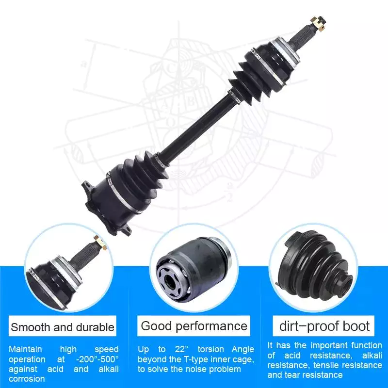
Vehicles with three axles

There are many different types of vehicles with three axles. Some of the most common include the dump truck, Greyhound bus, and tractor-trailer. Vehicles with three axles are generally heavier than four-axle vehicles. Vehicles with three axles have two sets of wheels – one front and one back. For example, a heavy truck will have three rear axles, a semi-trailer will have two front axles, and a tow truck will have two drive axles and two steer axles.
A vehicle’s axle count can vary. A simple method of figuring out the number of axles in a vehicle is to count the wheels. There are many ways to find out the number of axles on a vehicle. You can also look in the owner’s manual or ask a mechanic. If you’re unsure, ask someone who knows how to tell if a vehicle has three or four axles.
The design of a vehicle’s axles has several benefits. One of these benefits is its ability to disperse weight across a larger area, thereby reducing the risk of the vehicle sinking into soft ground. Dump trucks often drive to delivery sites with the third axle raised, lowering it only when it’s time to cross a soft area.
The number of axles in a vehicle is a crucial factor in determining how much power it needs to move. Different vehicles are designed to handle different terrains and have different axles to match their needs. For example, two-axle vehicles have two front axles, while three-axle vehicles have three rear axles.
A front axle is located at the front of the vehicle and helps with steering and processing road shocks. A front axle is often made of carbon steel, while a stub axle is a fixed axle that supports only one wheel. The front axle is connected to the stub axle through a kingpin.
Vehicles with three axles are generally larger than two axle vehicles. However, some two-axle vehicles can be three-axle, especially if they have a trailer. The design of a vehicle with three axles depends on what type of trailer it has. A two-axle trailer will usually have a trailer attached to it, and the rear axle will be responsible for moving power from the differential to the rear wheels.
Unlike semi-floating axles, full-floating axles are supported by two large bearings. They’re used for larger vehicles with high towing capacities. They also help with wheel alignment. A three-quarter floating axle is more complex than a semi-floating axle, and is often found in mid-size trucks.
There are also vehicles with a middle axle. Figures 2 and 3 illustrate this arrangement. The front and rear axles support most of the weight of the vehicle and the secondary axle has almost no ground weight. The secondary axle has a ground weight that is only 8.5% of the vehicle’s unloaded weight. The wheels of the vehicle remain in contact with the ground. Leaf spring 1 is coupled to the middle secondary axle.
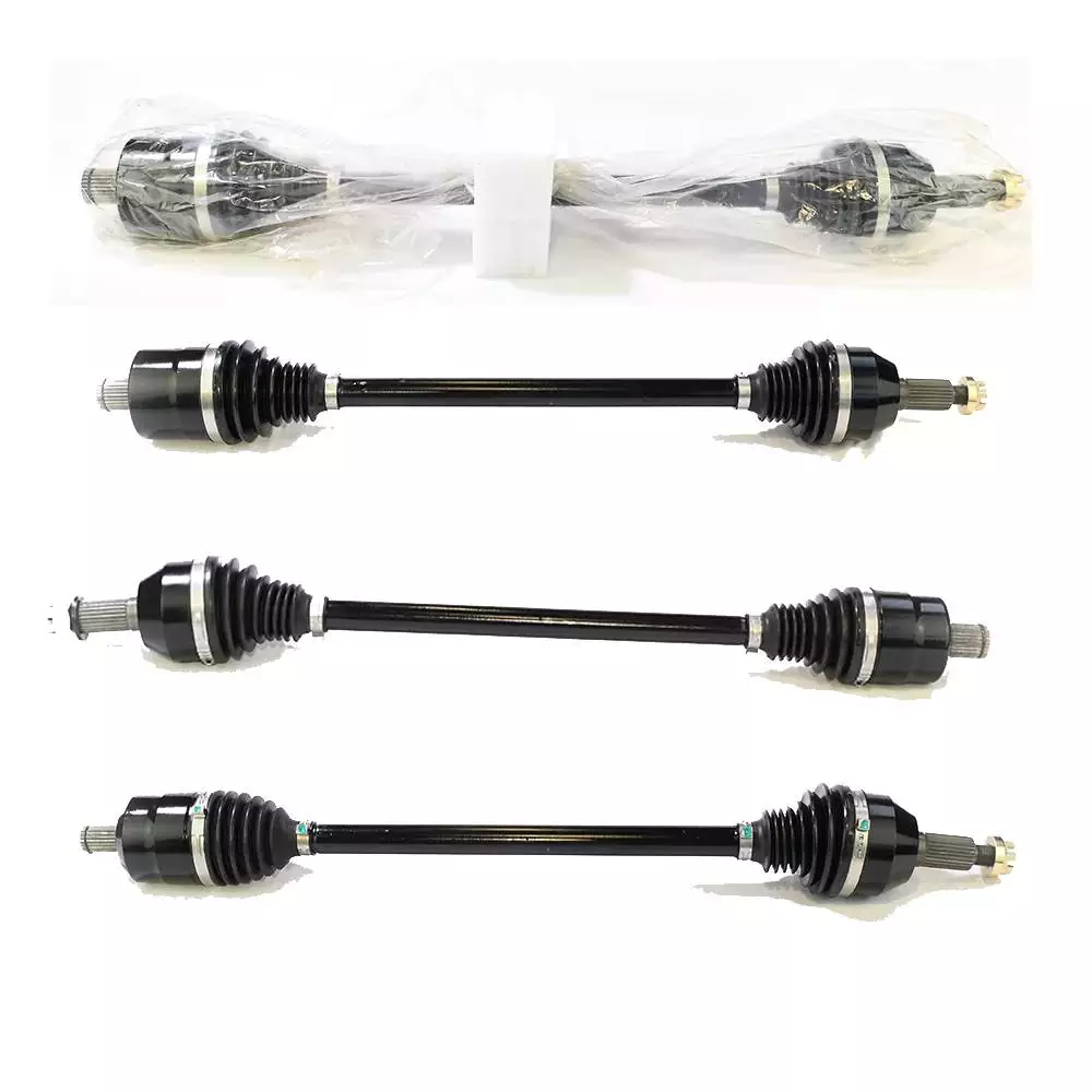
Types of axles

There are several different types of axles, and each is different in function. Some have bearings on each end, while others don’t. These two types of axles have different strengths and weaknesses, so it’s important to know which one is right for you. The best axle for your vehicle depends on your driving needs and budget.
The most basic type of axle is the axle shaft. This is the most inexpensive kind of axle. It connects the wheel hub to the axle shaft. The axle shaft is attached to the wheel hub by bolts. The wheel axle sits in the middle of the axle shaft. The bearings and axle casing transfer the weight of the wheel to the axle. The bearings are designed to distribute the weight evenly on both sides of the axle.
Another type of axle is the reverse Czpt stub axle. It is similar to the standard Czpt stub axle, but the reverse Czpt is designed with an L-shaped spindle. The rear axles also come in different types. These depend on how they are mounted on the vehicle. There are three different types of rear axles: rigid axles, semi-floating axles, and floating axles.
A full floating axle, on the other hand, does not support the weight of the vehicle. It is attached to the wheel hub and axle housing. It is most common in trucks and heavy duty vehicles. These axles are also the most durable, but they can only handle a heavy load. If the axle shaft breaks or is damaged, the vehicle will drop.
The type of axles a vehicle has is important because it affects the turning radius. A single axle vehicle has one drive axle at the rear, while a tandem vehicle has two drives. This means that the vehicle has a larger turning radius than a single axle one. There are also a variety of designs that allow it to turn at higher speeds and with less torque.
Lastly, a dead front axle is an immovable front axle, not revolving with the wheels. It is protected by housings and is a good choice for vehicles that cannot be driven in wet conditions. They provide the driving power from the Axles to the front wheels. The Czpt type uses a kingpin, while the Lamoine type uses a yoke-type hinge.
Three quarter floating axles are a hybrid between a full and semi floating axle. In this type, the axle is attached to the hub through bearings. As a result, it eliminates the shearing stress of the axle and focuses on bending loads. These axles are cheaper than the semi-floating type, and they are used in lighter trucks.
A semi-floating axle, on the other hand, has a bearing inside its axle casing. This axle is a lightweight option that still supports all the vehicle’s weight. This axle is generally used on light-duty pickups and mid-size trucks.
China Custom Available CZPT in Bulk Landing Gear 13ton Trailer Axle with ISO/Ts16949   axle boltChina Custom Available CZPT in Bulk Landing Gear 13ton Trailer Axle with ISO/Ts16949   axle bolt
editor by CX 2023-05-19

China Factory Price CFmOTO 500CC 600CC ATV Parts X5 X6 X8 0180-330010 REAE AXLE Rear Trassmission BEVEL GEAR COMP wholesaler

Model Quantity: 0180-33571
Content: metallic
Item Name: REAR AXLE REAR DIFFERENTIAL BEVEL Equipment COMP
Shade: Silver
Shipping: Convey
Fat: 4.5kg
Suit for: CF MOTO ATV UTV
Manufacturer: LIEQIMC
Packaging Particulars: STHangZhouRD PACKING OR as customer`s particular ask for.

Specification

Area Of OriginZheJiang ,China
ColourGrey
Technological innovationFinishing
TextureMetal
Brand IdentifyLIEQIMC
Good qualityLarge top quality
Business Profile Packing & Supply FAQ Q1: What type of business are we? A: We are an integrated generation and trade organization. Most of our goods are produced by ourselves, and some equipment aresent right from Cfmoto to clientsQ2: Our consumer distribution spotA: Our business is based in ZheJiang , China begin from 2017,market to North The us(21.00%), SouthAmerica(20.00%),EasternEurope(fourteen.00%),CentralAmerica(thirteen.00%),SouthernEurope(ten.00%),NorthernEurope(9.00%),WesternEurope(8.00%),Oceania(5.00%).There are whole about eleven-50 folks in our place of work.Q3: how can we promise quality?A: Always a pre-production sample just before mass productionAlways ultimate Inspection just before cargo.This fall: what can you buy from us?Atv spare areas,utv spare components,motorcycle spare parts,vehicle parts,gear box,spare parts.Q5: why need to you purchase from us not from other suppliers?1).Original elements with superior quality2).High quality guarantee Has long guarantee time3). Sensible price4).Quick delivery time and low cost worldwide transportation5).Can get sample manufacturing 6).Entire refund agreement 7).Heat provider and smooth interaction Reply in 24 hours.8).Confidentiality for consumers 9).There is a complex group can reply all technical questions for you10). quickly shipping and deliveryQ6: what solutions can we provide?A: Accepted Supply Conditions: FOB,CFR,CIF, tractor spare components cardan pto travel shafts for Iseki ,kubota Tractors EXW,FAS,CIP,FCA,CPT,DEQ,DDP,DDU,Express Delivery,DAF,DES;Accepted Payment Forex:USD,EUR,JPY,CAD,AUD,HKD,GBP,CNY,CHFAccepted Payment Sort: T/T,L/C, Cheap Hot Sale Bearings Pillow Block Bearing SA208 SA209 SA210 SA211 D/P D/A,MoneyGram,Credit Card,PayPal,Western Union,Income,EscrowLanguage Spoken:English,Chinese,Spanish,Japanese,Portuguese,German,Arabic,French,Russian,Korean,Hindi,Italian.Q7: Can we ship the sample?We can deliver the sample, but we want to pay the sample charge)Q8: How prolonged is the warranty?A: All our products are confirmed for 1 calendar year from the day of saleQ9:What if you are not happy with the quality?You can use for a entire refund if you are not happy with the top quality

Understanding the Working of an Axle

An axle is the central shaft of a rotating gear or wheel. It can be fixed to wheels or to the vehicle and can rotate along with them. The axle may include a number of bearings and other mounting points. Axles are essential for the operation of many types of vehicles. To understand the working of an axle, you should understand its basic purpose.
Axles

Vehicles with two axles

There are many different types of vehicles, but most are characterized by having two axles. Two axles are common in SUVs, trucks, and other vehicles that are meant to be off-road or for light hauling. Vehicles with two axles also include light-duty cargo vans and passenger cars.
There are many different kinds of two-axle vehicles, ranging from bicycles to motorcycles. In the United States, the most common kind of two-axle vehicles are pickup trucks, SUVs, and sedans. Three-axle vehicles are also common, with the largest type being tractor-trailers. Four-axle vehicles are rare, though. Some class 8 trucks have two-axle tractors.
Two-axle vehicles typically have two axles, with one axle supporting each of the two wheels. Other types of vehicles have three or four axles. The more axles a vehicle has, the more stability it has and the more weight it can handle. Two-axle vehicles are common, but three-axle vehicles are popular in transporting large cargo. Some are even designed with raised axles.
The number of axles on a car depends on its size and purpose. A car has a front axle and a rear axle. The front axle steers the vehicle, and the rear axle powers the wheels. The number of axles in a truck is largely dependent on its size and load, and some trucks have as many as four.
The front axle and rear axle are connected by a drive shaft. The driveshaft connects to the engine, which turns the axles. The two axles transfer the power from the engine to the wheels, and they may also help drive the vehicle. Axles are essential components of a vehicle, and should be strong and durable.
Axles are also important for a vehicle’s turning radius. Heavy-duty vehicles, such as semi-trucks, have large turning radii. Because they run across the width of the vehicle, axles make it possible for the wheels to turn freely. In addition to allowing the wheels to turn, they also support the weight of the vehicle.
Typical vehicles with two axles include the Toyota Rav4 and the Ford Mustang. The Rav4 uses two axles in front and rear-wheel drive. The Ford Mustang, on the other hand, has a live rear axle. In addition, the Mustang is also two axles. A tandem axle is an arrangement of two rear axles close together. It is a popular style in large vehicles.

Vehicles with three axles

There are many different types of vehicles with three axles. Some of the most common include the dump truck, Greyhound bus, and tractor-trailer. Vehicles with three axles are generally heavier than four-axle vehicles. Vehicles with three axles have two sets of wheels – one front and one back. For example, a heavy truck will have three rear axles, a semi-trailer will have two front axles, and a tow truck will have two drive axles and two steer axles.
A vehicle’s axle count can vary. A simple method of figuring out the number of axles in a vehicle is to count the wheels. There are many ways to find out the number of axles on a vehicle. You can also look in the owner’s manual or ask a mechanic. If you’re unsure, ask someone who knows how to tell if a vehicle has three or four axles.
The design of a vehicle’s axles has several benefits. One of these benefits is its ability to disperse weight across a larger area, thereby reducing the risk of the vehicle sinking into soft ground. Dump trucks often drive to delivery sites with the third axle raised, lowering it only when it’s time to cross a soft area.
The number of axles in a vehicle is a crucial factor in determining how much power it needs to move. Different vehicles are designed to handle different terrains and have different axles to match their needs. For example, two-axle vehicles have two front axles, while three-axle vehicles have three rear axles.
A front axle is located at the front of the vehicle and helps with steering and processing road shocks. A front axle is often made of carbon steel, while a stub axle is a fixed axle that supports only one wheel. The front axle is connected to the stub axle through a kingpin.
Vehicles with three axles are generally larger than two axle vehicles. However, some two-axle vehicles can be three-axle, especially if they have a trailer. The design of a vehicle with three axles depends on what type of trailer it has. A two-axle trailer will usually have a trailer attached to it, and the rear axle will be responsible for moving power from the differential to the rear wheels.
Unlike semi-floating axles, full-floating axles are supported by two large bearings. They’re used for larger vehicles with high towing capacities. They also help with wheel alignment. A three-quarter floating axle is more complex than a semi-floating axle, and is often found in mid-size trucks.
There are also vehicles with a middle axle. Figures 2 and 3 illustrate this arrangement. The front and rear axles support most of the weight of the vehicle and the secondary axle has almost no ground weight. The secondary axle has a ground weight that is only 8.5% of the vehicle’s unloaded weight. The wheels of the vehicle remain in contact with the ground. Leaf spring 1 is coupled to the middle secondary axle.

Types of axles

There are several different types of axles, and each is different in function. Some have bearings on each end, while others don’t. These two types of axles have different strengths and weaknesses, so it’s important to know which one is right for you. The best axle for your vehicle depends on your driving needs and budget.
The most basic type of axle is the axle shaft. This is the most inexpensive kind of axle. It connects the wheel hub to the axle shaft. The axle shaft is attached to the wheel hub by bolts. The wheel axle sits in the middle of the axle shaft. The bearings and axle casing transfer the weight of the wheel to the axle. The bearings are designed to distribute the weight evenly on both sides of the axle.
Another type of axle is the reverse Czpt stub axle. It is similar to the standard Czpt stub axle, but the reverse Czpt is designed with an L-shaped spindle. The rear axles also come in different types. These depend on how they are mounted on the vehicle. There are three different types of rear axles: rigid axles, semi-floating axles, and floating axles.
A full floating axle, on the other hand, does not support the weight of the vehicle. It is attached to the wheel hub and axle housing. It is most common in trucks and heavy duty vehicles. These axles are also the most durable, but they can only handle a heavy load. If the axle shaft breaks or is damaged, the vehicle will drop.
The type of axles a vehicle has is important because it affects the turning radius. A single axle vehicle has one drive axle at the rear, while a tandem vehicle has two drives. This means that the vehicle has a larger turning radius than a single axle one. There are also a variety of designs that allow it to turn at higher speeds and with less torque.
Lastly, a dead front axle is an immovable front axle, not revolving with the wheels. It is protected by housings and is a good choice for vehicles that cannot be driven in wet conditions. They provide the driving power from the Axles to the front wheels. The Czpt type uses a kingpin, while the Lamoine type uses a yoke-type hinge.
Three quarter floating axles are a hybrid between a full and semi floating axle. In this type, the axle is attached to the hub through bearings. As a result, it eliminates the shearing stress of the axle and focuses on bending loads. These axles are cheaper than the semi-floating type, and they are used in lighter trucks.
A semi-floating axle, on the other hand, has a bearing inside its axle casing. This axle is a lightweight option that still supports all the vehicle’s weight. This axle is generally used on light-duty pickups and mid-size trucks.
China Factory Price CFmOTO 500CC 600CC ATV Parts X5 X6 X8 0180-330010 REAE AXLE Rear Trassmission BEVEL GEAR COMP     wholesaler China Factory Price CFmOTO 500CC 600CC ATV Parts X5 X6 X8 0180-330010 REAE AXLE Rear Trassmission BEVEL GEAR COMP     wholesaler
editor by czh 2023-03-12

China Axle Parts Half Shaft Gear Front 199114320032forhowo Ankai Middle Axle cv axle puller

Product Description

Axle areas 50 percent shaft equipment  front for HOWO  ANKAI Middle axle


Firm ChinaMach Market Co.,Ltd
Model SINOTRUK HOWO/WEICHAI/Gentleman/SHACMAN/FAW/FOTON/AUMAN/NORTHBENZ/SANY/XCMG/SHXIHU (WEST LAKE) DIS.I/SDLG
Top quality Authentic component/OE component
Payment expression T/T L/C , Flexible billing approach
Packing Standard packing

We can give:
TRUCK
Sales Chinese trucks and development equipment,Give modificationsu,pgrades, consulting companies
SPARE TRUCK
Provide China Truck spare components and design machinery areas. Products Include:  Sinotruk HOWO, CZPT , Fonton, Shacman,SHXIHU (WEST LAKE) DIS.I, CZPT ,SDLG
Provider
Provide cargo warehousing, packaging, transport and export company companies
Agent procurement, inspection The inspection agency 


US $1
/ Piece
|
1 Piece

(Min. Order)

###

Material: Steel
Muffler Type: Rear Muffler
Brand: Sinotruk
Name: Half Shaft Gear Front
Transport Package: Wooden
Specification: 199114320032

###

Samples:
US$ 1/Piece
1 Piece(Min.Order)

|
Request Sample

###

Customization:

###

Company ChinaMach Industry Co.,Ltd
Brand SINOTRUK HOWO/WEICHAI/MAN/SHACMAN/FAW/FOTON/AUMAN/NORTHBENZ/SANY/XCMG/SHANTUI/SDLG
QUALITY Original part/OE part
Payment term T/T L/C , Flexible billing method
Packing Standard packing

Different Types of Axles

An axle is the central shaft of a gear or wheel. It can be mounted to a wheel or to the vehicle itself, and will rotate with the wheels and vehicle. It may also contain bearings. Some vehicles have different types of axles, including Live, Split, Tandem, and Drop-out axles.

Live axle

A beam axle, also called a rigid axle, is a type of dependent suspension system. It connects a set of wheels lateral to one another. In previous times, beam axles were used in the rear of a vehicle, and later on, as the front axle in four-wheel-drive vehicles.
Live axles are also popular on trucks. They can provide better traction and keep the vehicle at a constant height. This is especially helpful for off-road vehicles. Those vehicles are typically driven slowly and the suspension is not as important as handling and cornering. Nonetheless, some trucks still use this design. It can be a great option if you are looking for a vehicle that handles well.
Live axles have a number of drawbacks. The front end of a live axle can destabilize and affect cornering grip. They also require a means of locating the axle, which may be an issue with heavy or lightweight vehicles. Leaf springs can help in this regard. Alternatively, you can opt for an independent rear axle.
Live axles are a great option for drag racing vehicles. They offer better traction and a better structural base than a conventional full floater axle assembly. They also allow for increased gear life and reduce rear end distortion.
Axles

Split-axle

If you aren’t sure how to make split axles, you’re not alone. The process can be very difficult, and the parts can get mixed up. The key is to know how to create the proper alignment for your axles. Thankfully, there are some tools that can make this job a breeze.
Split axles have two components: a bolt head 30 that acts as a stop during relative pivotal movement. The axle assembly 16 is then pivotally mounted between the brackets and the frame. During pivotal movement, the bolt head 30 acts as a stop and prevents the axle from moving too far either way. This is done to maintain the pad 28 at a predetermined compression level. This allows the axle to perform a smooth and consistent drive.
Split axles are a common feature of modern vehicles. This type of suspension system provides greater traction, and it allows the left and right wheels to roll at different speeds. It also prolongs the life of tires, and increases traction.

Tandem

A tandem axle trailer is a great choice for hauling large loads. This style of trailer comes with more features and is more stable. These trailers are usually available in 16′, 18′, or 20′ lengths. They are also available with 8,500, or 10,000 GVW capacities. They are a great choice for hauling large loads on main highways.
Tandem axles are commonly used on trucks. Each axle features a drive mechanism, and are attached to the engine power unit. There are two types of tandem axles, one with a standard differential and the other with a power divider. Drivers may have trouble figuring out which axle is driving the truck at different times, so it is important to understand how each type of axle works.
While there are some common rules that apply to tandem axles, there are also some exceptions. In some cases, a single axle has a lower weight limit than a tandem axle, and the two axles must be at least 40 inches apart.

Drop-out

Drop-out axles are used to connect the dropouts of a bike frame. When using dropouts, make sure the distance between the axles is 110mm. Then use a clamp to squeeze the dropouts together. Make sure to measure both dropouts carefully, because a 1mm difference in the width can cause a lot of trouble.
The 9″ drop-out axle was produced from the late 1950s to 1986. They were made in trucks and cars, but not in motorcycles. To use this axle in a 1990 LTD CV, you will need to make several modifications to the mounting of the axle and connection to the drive line. You will also need to consider installing a parking brake. Moreover, this axle is not compatible with the Panther platform. In fact, the drop-out axle is available in several variations.
Drop-out axles are also known as single-speed. The lower part is called the semi-horizontal dropout, while the upper part is called the vertical dropout. This dropout includes an eyelet for mounting a fender or rack.
Axles

Czpt

The Czpt axle is a popular choice for a wide variety of vehicles. Initially used in heavy-duty pickup trucks, it was eventually adopted by all major automakers in the U.S., including Ford, Dodge, and Chrysler. It also became popular as a front differential on 4WD vehicles.
Czpt axles are easy to recognize, and the numbering system is consistent regardless of the vehicle model. The axle’s model number is found on the right lower web of the housing near the pinion yoke. It is also stamped on the axle tube. If you can’t find the axle model number, you can find it on Czpt’s website.
Czpt axles are also recognizable by their Bill of Materials (BOM) number. This is like a vehicle’s VIN number, and it identifies the axle’s gear ratio, model number, and component parts. A Czpt axle’s BOM number starts with 60 or 61.
The Czpt axle is the most common axle size in Jeeps. The Czpt 30 axle is the standard, and can be found on most Jeeps. The YJ version of this axle uses a reverse cut ring and pinion, while the TJ version does not. It is made from 5×4.5 inch bolts.

Universal joint

A universal joint is a component that connects two wheels to one another. This component is made to replace worn out or damaged parts on axles. They are also used to repair and replace brakes and drive shaft yokes. The universal joint can be purchased at an auto parts store or online. To replace a universal joint, you need to remove the axle shaft and the front brakes.
The universal joint is a flexible pivot point that transfers power between two shafts. In order to work properly, it must be flexible enough to compensate for changes in the driveline angle. These changes may be due to changing terrain. The universal joint is an important part of the driveline. It is used in both manual and automatic transmissions.
A universal joint should be serviced regularly to maintain its performance. If your universal joint squeaks while driving, it is a sign that it needs to be serviced. A lubricant can help extend the life of a u-joint.
Axles

Spindle

Your vehicle’s axle consists of two main components: the hub and the spindle. The spindle rides on the hub, which can become damaged or lose its shape when it hits something. The spindle is also prone to wear from high mileage, and its threads can be damaged. If you suspect that your spindle needs to be replaced, there are several options available.
Axle spindles can be installed in one of three ways. The typical assembly includes bolted spindles on the ends of a tubular axle. The axle is then suspended by springs. Another type of mounting involves a torsion beam on the axle leg, which acts as a spring. It flexes and bends to provide the turning motion. The axle spindle can be a replacement part for your trailer, and there are towing supplies and professionals who can do it for you.
China Axle Parts Half Shaft Gear Front 199114320032forhowo Ankai Middle Axle     cv axle pullerChina Axle Parts Half Shaft Gear Front 199114320032forhowo Ankai Middle Axle     cv axle puller
editor by czh 2022-12-12

China Custom Drive Axle Spiral Bevel Gear Cone Gear 937h 936 933 Zl30h Wheel Loader CZPT with Great quality

Product Description

Machine Model: 937H 936 933 ZL30H Sinomach Xihu (West Lake) Dis.n
Model NO: Z-13E-060-Z0001
Part drawing No: Z30E.6.2.Z1
Color: Gray-Black
Advantage: Good Mechanical Properties
Toothed Portion Shape: Spiral Bevel Gear
Manufacturing Method: Forging Gear 
Deliver Time: 5 to 7 working days after receiving the advance payment

Spare parts of Sinomach Xihu (West Lake) Dis.n including:Engine system,Torque Converter and Transmission system,Power train, Hydraulic system,Brake system,Cab and accessorie,Conditioner system,Electrical system,Oil product, etc.
High quality products,enough stock,30 years export experience,we can offer professional service and competitive prices for you .
Sinomach Xihu (West Lake) Dis.n looking forward to cooperation with you.
Advantages of Sinomach Xihu (West Lake) Dis.n drive axle:
1. The drive axle housing adopts integral steel castings. The material has excellent mechanical properties, good rigidity and high strength, and can meet the needs of various complex working conditions.
2. The spiral bevel gear is made of alloy structural steel and designed with 35 ° spiral angle, which can bear high load.
3. The brake disc is made of gray cast iron, which has high wear resistance and ensures the ideal friction coefficient.

Parts warehouse

packaging and Shipping

Company Profile

FAQ
1. What is your terms of payment?
T/T 30% as deposit, and balance paid before delivery(We’ll show you the all pictures of the products and packages before paying the balance)

2.How about your delivery time?
Generally, it will take 5 to 7 working days after receiving your advance payment. The specific delivery time depends on the quantity of your order.

3. Do you test all your goods before delivery?
A: Yes, we will have 100% test and double check before delivery.

4. How do you make our business long-term and good relationship?
(1) We keep good quality and competitive price to ensure our customers benefit 
(2) We respect every customer as our friend and we sincerely do business and make friends with them, no matter where they come from.

5.After -sales service
We have QC department to guarantee the quality before delivery, If the products have any quality problems, our company will be responsible for it.

6.What kind of package?
Wooden cases, cartons, or the packaging you specify.
 

Axle Spindle Types and Features

The axle spindle is an integral part of your vehicle’s suspension. There are several different types and features, including mounting methods, bearings, and functions. Read on for some basic information on axle spindles. The next part of the article will cover how to choose the correct axle spindle for your vehicle. This article will also discuss the different types of spindles available, including the differences between the rear and front bearings.
Driveshaft

Features

The improved axle spindle nut assembly is capable of providing additional performance benefits, including increased tire life and reduced seal failure. Its keyway features and radially inwardly extending teeth allow nut adjustment to be accomplished with precision. The invention further provides a unique, multi-piece locking mechanism that minimizes leakage and torque transfer. Its principles and features are detailed in the appended claims. For example, the improved axle spindle nut assembly is designed for use in vehicles that are equipped with a steering system.
The axle spindle nut assembly includes a nut 252 with threads 256 on its inner periphery. The axle spindle 50 also features threads 198 on its outer periphery. The nut is threaded onto the outboard end of the axle spindle 50 until it contacts the inboard surface of the axle spacer 26. In the assembled state, a bearing spacer 58 is also present on the axle spindle.
The axle spindle nut assembly can reduce axial end play between the wheel end assembly 52 and the axle spindle 50. It can be tightened to an extreme torque level, but if the thread faces separate, it will undercompress the bearing cone and spacer group. To minimize these disadvantages, the axle spindle nut assembly is a critical component of a wheel-end assembly. There are several types of axle spindle nuts.
The third embodiment of the axle spindle nut assembly 300 comprises an inner washer 202, an outer washer 310, and at least 1 screw 320. The axle spindle nut assembly 300 secures and preloads bearing cones 55, 57. Unlike the first embodiment, the axle spindle nut assembly 300 uses the inner washer 202, which is optional in the third embodiment. The inner washer 202 and outer washer 310 are similar to those of the first embodiment.

Functions

An axle spindle is 1 of the most important components of a vehicle’s suspension system. The spindle retains the position of bearings and a spacer in an axle by providing clamp force. The inner nut of an axle spindle should be properly torqued to ensure a secure fit. A spindle nut is also responsible for compressing bearings and spacers. If any of these components are missing, the spindle will not work properly.
An axle spindle is used in rear wheel drive cars. It carries the weight of the vehicle on the axle casing and transfers the torque from the differential to the wheels. The axle spindle and hub are secured on the spindle by large nuts. The axle spindle is a vital component of rear wheel drive vehicles. Hence, it is essential to understand the functions of axle spindle. These components are responsible for the smooth operation of a vehicle’s suspension system.
Axle spindles can be mounted in 3 ways: in the typical axle assembly, the spindles are bolted onto the ends of the tubular axle, and the axle is suspended by springs. Short stub-axle mounting uses a torsion beam that flexes to provide a smooth ride. A second washer is used to prevent excessive rotation of the axle spindle.
Apart from being a crucial component of the suspension system, the spindles of the wheels are responsible for guiding the vehicle in a straight line. They are connected to the steering axis and are used in different types of suspension systems. European cars use a MacPherson Strut suspension system in which the spindle is connected to the arms in the front and rear of the suspension frame. The MacPherson strut allows the shock absorber housing to turn the wheel.
Driveshaft

Methods of mounting

Various methods of mounting axle spindle are available. In general, these methods involve forming a tubular blank of uniform cross section and thickness, and receiving the bearing assembly against it. The spindle is then secured using a collar, which also serves as a bearing stop. In some cases, additional features are used to provide greater security. Some of these features may not be suitable for all applications. But they are generally suitable.
Axle spindle forming is usually done by progressive steps using hollow punches. The metallic body of the punch has an inner work surface, which receives the axle blank. A mandrel is fixed within the work opening of the punch. The punch body’s work surface forges the spindle about the mandrel. The punch has 2 ends, a closed and an open one.
A wheeled vehicle axle assembly (10) includes a cylindrical housing member (12 a) and a plurality of spindle mounting flanges (30) secured on the housing member. The spindles (16) are firmly attached to the housing member by means of coupling members. The coupling members are configured to distribute the bending loads imposed on the spindle by the axle. It is important to note that the coupling members can be either threaded or screwed.
Traditionally, axle spindles were made from tubular blanks of irregular thickness. This method allowed for a gradual reduction in diameter and eliminated the need for extra metal within the spindle. Similarly, axles made by cold forming eliminate the need for additional metal in the spindle. In this way, the overall cost of manufacture is also reduced. The material used for manufacturing axles also determines the size and shape of the final product.
Driveshaft

Bearings

A nut 16 is used to retain the wheel bearings on axle spindle 12. The nut comprises several parts. The first portion includes a plurality of threads and a deformable second portion. The nut may be disposed on the inboard or outboard end of the axle spindle. This type of nut is typically secured to the axle spindle by a retaining nut.
The bearings are installed in the spindle to allow the wheel hub to rotate. While bearings are greased, they can dry out over time. Consequently, you may hear a loud clicking sound when turning your vehicle. Alternatively, you may notice grease on the edges of your tires. Bearing failure can cause severe damage to your axle spindle. If you notice any of these symptoms, you may need to replace the bearings on your axle spindle. Fortunately, you can purchase the necessary bearing parts at O’Reilly Auto Parts.
There are 3 ways to mount an axle spindle. A typical axle assembly has the spindles bolted to the ends of the tubular axle. A torsion beam is also used to mount the spindles on the axle. This torsion beam acts like a spring to help make the ride smooth and bump-free. Lastly, the axle spindle is sometimes mounted as a bolt-on component.

Cost

If your axle spindle has been damaged, you may need to have it replaced. This part of the axle is relatively easy to replace, but you need to know how to do it correctly. To replace your axle spindle, you must first remove the damaged one. To do this, a technician will cut the weld. They will then thread the new 1 into the axle tube and torque it to specification. After that, they will weld the new axle spindle into place.
When you are thinking about the cost of an axle spindle replacement, you must first determine if it is worth it for your vehicle. It is generally a good idea to replace the spindle only if it is causing damage to your vehicle. You can also replace your axle housing if it is deteriorating. If you do not replace the spindle, you can risk damaging the axle housing. To save money, you can consider using a repair kit.
You can also purchase an axle nut socket set. Most wrenches have an adjusting socket for this purpose. The socket set should be suitable for most vehicle types. Axle spindle replacement costs around $500 to $600 before tax. However, you should be aware that these costs vary widely based on the type of vehicle you have. The parts can cost between $430 and $480, and the labor can cost anywhere from $50 to 70.

China Custom Drive Axle Spiral Bevel Gear Cone Gear 937h 936 933 Zl30h Wheel Loader CZPT   with Great qualityChina Custom Drive Axle Spiral Bevel Gear Cone Gear 937h 936 933 Zl30h Wheel Loader CZPT   with Great quality

China high quality Hot High Speed Stacking Gear Drive 4 Color T-Shirt Plastic Bag Flexo Printing Machine for Sale Price near me manufacturer

Product Description

Main Parameter
 

items describe
Maximum paper width 1050mm
Maximum printing width 1000mm
Registration Precision 0.1mm
Printing repeat 300-600mm
Maximum unwinding dia 1500mm
Maximum rewinding dia 1500mm
Unwinding type Air shaft
Rewinding type Surface tension
Gear format 5mm per tooth
The speed 150-200m/min
The thickness of plate 2.28mm
The thickness of tape 0.38mm
Suitable materials Paper cup, paper box etc
The color of machine Grey and white
Operation language Chinese
Air comsuption 6KG, 0.6L/Min clear,dry,no water/oil AIR
Voltage required 380 VAC +/-10%   3PH  50HZ
Dry type Electric heating,Heating power27KW
Total power 102kw
Dimension 7600*2700*3400mm


Samples reference
 

Certifications

ISO &CE certification
 

Win-win cooperation with clients

Container loading


FAQ

Q: What types of machines do you have? How long has your factory been in this field?
We have more than 10 years of experience in manufacturing Roll Die Cutting Machine, Roll Die Punching Machine, Carton Erecting Machine, Paper Box Forming Machine, Paper Cake Box Machine, Flexo Printing Machine, Cartoning Machine working with listed packaging companies for KFC, Mcdonald’s, Subway, Starbucks.

Q: Where is the factory located?
We are located in Xihu (West Lake) Dis. Town, Xihu (West Lake) Dis.. It takes 10 minutes by car from HangZhou Train Station and 1 hour from HangZhou International Airport.

Q: What Is the machine delivery time? What is the packing way for delivery?
Generally speaking, the CI flexo printing machine could be shipped out within 60-90 days after confirming everything. And it will be packed by flexible packaging with an iron underframe.

Q: How about the machine guarantee?
During 1 year, for any parts damaged caused by the machine-self, the seller will repair/replace the spare parts for free, but the buyer should pay the freight. After 1 year, the seller will supply the spare parts to buyers at the cost. The machine service is all around the machine life.

 QHow about after-sales?
Based on our strong after-sales team and rich experience, we can resolve most of the problems online by video call, messages, and e-mail.

Q: Does Feida accept customized machines?
Yes, we could design the machine based on the customer’s requirements.

Q: What is Feida’s working time?
24 hours online,  but we will reply to messages from 7:30 am to 00:00 per day.
 

How to Calculate Stiffness, Centering Force, Wear and Fatigue Failure of Spline Couplings

There are various types of spline couplings. These couplings have several important properties. These properties are: Stiffness, Involute splines, Misalignment, Wear and fatigue failure. To understand how these characteristics relate to spline couplings, read this article. It will give you the necessary knowledge to determine which type of coupling best suits your needs. Keeping in mind that spline couplings are usually spherical in shape, they are made of steel.
splineshaft

Involute splines

An effective side interference condition minimizes gear misalignment. When 2 splines are coupled with no spline misalignment, the maximum tensile root stress shifts to the left by 5 mm. A linear lead variation, which results from multiple connections along the length of the spline contact, increases the effective clearance or interference by a given percentage. This type of misalignment is undesirable for coupling high-speed equipment.
Involute splines are often used in gearboxes. These splines transmit high torque, and are better able to distribute load among multiple teeth throughout the coupling circumference. The involute profile and lead errors are related to the spacing between spline teeth and keyways. For coupling applications, industry practices use splines with 25 to 50-percent of spline teeth engaged. This load distribution is more uniform than that of conventional single-key couplings.
To determine the optimal tooth engagement for an involved spline coupling, Xiangzhen Xue and colleagues used a computer model to simulate the stress applied to the splines. The results from this study showed that a “permissible” Ruiz parameter should be used in coupling. By predicting the amount of wear and tear on a crowned spline, the researchers could accurately predict how much damage the components will sustain during the coupling process.
There are several ways to determine the optimal pressure angle for an involute spline. Involute splines are commonly measured using a pressure angle of 30 degrees. Similar to gears, involute splines are typically tested through a measurement over pins. This involves inserting specific-sized wires between gear teeth and measuring the distance between them. This method can tell whether the gear has a proper tooth profile.
The spline system shown in Figure 1 illustrates a vibration model. This simulation allows the user to understand how involute splines are used in coupling. The vibration model shows 4 concentrated mass blocks that represent the prime mover, the internal spline, and the load. It is important to note that the meshing deformation function represents the forces acting on these 3 components.
splineshaft

Stiffness of coupling

The calculation of stiffness of a spline coupling involves the measurement of its tooth engagement. In the following, we analyze the stiffness of a spline coupling with various types of teeth using 2 different methods. Direct inversion and blockwise inversion both reduce CPU time for stiffness calculation. However, they require evaluation submatrices. Here, we discuss the differences between these 2 methods.
The analytical model for spline couplings is derived in the second section. In the third section, the calculation process is explained in detail. We then validate this model against the FE method. Finally, we discuss the influence of stiffness nonlinearity on the rotor dynamics. Finally, we discuss the advantages and disadvantages of each method. We present a simple yet effective method for estimating the lateral stiffness of spline couplings.
The numerical calculation of the spline coupling is based on the semi-analytical spline load distribution model. This method involves refined contact grids and updating the compliance matrix at each iteration. Hence, it consumes significant computational time. Further, it is difficult to apply this method to the dynamic analysis of a rotor. This method has its own limitations and should be used only when the spline coupling is fully investigated.
The meshing force is the force generated by a misaligned spline coupling. It is related to the spline thickness and the transmitting torque of the rotor. The meshing force is also related to the dynamic vibration displacement. The result obtained from the meshing force analysis is given in Figures 7, 8, and 9.
The analysis presented in this paper aims to investigate the stiffness of spline couplings with a misaligned spline. Although the results of previous studies were accurate, some issues remained. For example, the misalignment of the spline may cause contact damages. The aim of this article is to investigate the problems associated with misaligned spline couplings and propose an analytical approach for estimating the contact pressure in a spline connection. We also compare our results to those obtained by pure numerical approaches.

Misalignment

To determine the centering force, the effective pressure angle must be known. Using the effective pressure angle, the centering force is calculated based on the maximum axial and radial loads and updated Dudley misalignment factors. The centering force is the maximum axial force that can be transmitted by friction. Several published misalignment factors are also included in the calculation. A new method is presented in this paper that considers the cam effect in the normal force.
In this new method, the stiffness along the spline joint can be integrated to obtain a global stiffness that is applicable to torsional vibration analysis. The stiffness of bearings can also be calculated at given levels of misalignment, allowing for accurate estimation of bearing dimensions. It is advisable to check the stiffness of bearings at all times to ensure that they are properly sized and aligned.
A misalignment in a spline coupling can result in wear or even failure. This is caused by an incorrectly aligned pitch profile. This problem is often overlooked, as the teeth are in contact throughout the involute profile. This causes the load to not be evenly distributed along the contact line. Consequently, it is important to consider the effect of misalignment on the contact force on the teeth of the spline coupling.
The centre of the male spline in Figure 2 is superposed on the female spline. The alignment meshing distances are also identical. Hence, the meshing force curves will change according to the dynamic vibration displacement. It is necessary to know the parameters of a spline coupling before implementing it. In this paper, the model for misalignment is presented for spline couplings and the related parameters.
Using a self-made spline coupling test rig, the effects of misalignment on a spline coupling are studied. In contrast to the typical spline coupling, misalignment in a spline coupling causes fretting wear at a specific position on the tooth surface. This is a leading cause of failure in these types of couplings.
splineshaft

Wear and fatigue failure

The failure of a spline coupling due to wear and fatigue is determined by the first occurrence of tooth wear and shaft misalignment. Standard design methods do not account for wear damage and assess the fatigue life with big approximations. Experimental investigations have been conducted to assess wear and fatigue damage in spline couplings. The tests were conducted on a dedicated test rig and special device connected to a standard fatigue machine. The working parameters such as torque, misalignment angle, and axial distance have been varied in order to measure fatigue damage. Over dimensioning has also been assessed.
During fatigue and wear, mechanical sliding takes place between the external and internal splines and results in catastrophic failure. The lack of literature on the wear and fatigue of spline couplings in aero-engines may be due to the lack of data on the coupling’s application. Wear and fatigue failure in splines depends on a number of factors, including the material pair, geometry, and lubrication conditions.
The analysis of spline couplings shows that over-dimensioning is common and leads to different damages in the system. Some of the major damages are wear, fretting, corrosion, and teeth fatigue. Noise problems have also been observed in industrial settings. However, it is difficult to evaluate the contact behavior of spline couplings, and numerical simulations are often hampered by the use of specific codes and the boundary element method.
The failure of a spline gear coupling was caused by fatigue, and the fracture initiated at the bottom corner radius of the keyway. The keyway and splines had been overloaded beyond their yield strength, and significant yielding was observed in the spline gear teeth. A fracture ring of non-standard alloy steel exhibited a sharp corner radius, which was a significant stress raiser.
Several components were studied to determine their life span. These components include the spline shaft, the sealing bolt, and the graphite ring. Each of these components has its own set of design parameters. However, there are similarities in the distributions of these components. Wear and fatigue failure of spline couplings can be attributed to a combination of the 3 factors. A failure mode is often defined as a non-linear distribution of stresses and strains.

China high quality Hot High Speed Stacking Gear Drive 4 Color T-Shirt Plastic Bag Flexo Printing Machine for Sale Price   near me manufacturer China high quality Hot High Speed Stacking Gear Drive 4 Color T-Shirt Plastic Bag Flexo Printing Machine for Sale Price   near me manufacturer

China manufacturer Customized Carbon Steel Hydraulic Drive Rail Gear with high quality

Product Description

Material

20CrMn5,20CrMnTi,40Cr,Powder deposit,45#steel,42CrMo,Stainless steel and so on as per your requests.

Custom

OEM/ODM

Lead Time

Sample: 20-30 days after deposit received, Batch goods: 30-45days after samples have been approved. Die opening product:7-15days after samples have been approved.It takes 45-60 days to open the mold.

Processing

Forging,Machining,Hobbing,Milling,Shaving,Grinding teeth, inserting teeth, shot blasting, Grinding,Heat treatment……

Heat Treatment

Intermediate frequency, high frequency, tempering, desalinating, carburizing……

Main Machines

CNC gear hobbing machine, CNC gear cutting machine, CNC lathe, CNC gear shaving machine, CNC gear milling machine, CNC gear grinding machine, CNC Grinding Machine….
..

Ruika has been engaged in manufacturing of forgings, castings, heat treatment and CNC machining parts since 1999.  

The products materials have passed EN15714-3.1 certification, covering various grades of: low carbon steel, alloy steel, stainless steel, ductile iron, aluminum alloy, copper alloy, titanium alloy. 

The main processes are: free forging, die forging, rolling ring, high pressure casting, centrifugal casting, normalizing, quenching and tempering, solution treatment, aging treatment, carbonitriding, turning, milling, drilling, grinding, hobbing, high frequency quenching, galvanizing, chrome plating, anodizing, powder spraying and other processes.

Rings and plates dimensions: Max 3000mm, shafts length: Max 12000mm, single piece weight: Max 16 Tons, at the same time we are good at terminal machining of complex products, dimension accuracy: Min 0.01mm, roughness: Min Ra0.6. 

Products can be strictly examined by chemical composition, tensile strength, yield strength, reduction of area, impact at low temperature, intergranular corrosion, hardness, metallographic, NDT, size, static balance etc performance parameter. 

Products are widely used in: aerospace, ships, trains, automobiles, engineering vehicles, chemical industry and petroleum refining, wellheads, x-mas tree equipment, mining machinery, food machinery, hydraulic and wind power generation, new energy equipment etc field. 

Welcome to send: PDF, IGS, STP and other format drawings, of course we could also make material judgment and size survey according to your samples. 

With more than 20 years of manufacturing experience and overseas sales team, we have achieved 100% customer satisfaction. The warranty period of products sold is 365 days. We look forward to your consultation and cooperation at any time and common prosperity development.

An Overview of Worm Shafts and Gears

This article provides an overview of worm shafts and gears, including the type of toothing and deflection they experience. Other topics covered include the use of aluminum versus bronze worm shafts, calculating worm shaft deflection and lubrication. A thorough understanding of these issues will help you to design better gearboxes and other worm gear mechanisms. For further information, please visit the related websites. We also hope that you will find this article informative.
worm shaft

Double throat worm gears

The pitch diameter of a worm and the pitch of its worm wheel must be equal. The 2 types of worm gears have the same pitch diameter, but the difference lies in their axial and circular pitches. The pitch diameter is the distance between the worm’s teeth along its axis and the pitch diameter of the larger gear. Worms are made with left-handed or right-handed threads. The lead of the worm is the distance a point on the thread travels during 1 revolution of the worm gear. The backlash measurement should be made in a few different places on the gear wheel, as a large amount of backlash implies tooth spacing.
A double-throat worm gear is designed for high-load applications. It provides the tightest connection between worm and gear. It is crucial to mount a worm gear assembly correctly. The keyway design requires several points of contact, which block shaft rotation and help transfer torque to the gear. After determining the location of the keyway, a hole is drilled into the hub, which is then screwed into the gear.
The dual-threaded design of worm gears allows them to withstand heavy loads without slipping or tearing out of the worm. A double-throat worm gear provides the tightest connection between worm and gear, and is therefore ideal for hoisting applications. The self-locking nature of the worm gear is another advantage. If the worm gears are designed well, they are excellent for reducing speeds, as they are self-locking.
When choosing a worm, the number of threads that a worm has is critical. Thread starts determine the reduction ratio of a pair, so the higher the threads, the greater the ratio. The same is true for the worm helix angles, which can be one, two, or 3 threads long. This varies between a single thread and a double-throat worm gear, and it is crucial to consider the helix angle when selecting a worm.
Double-throat worm gears differ in their profile from the actual gear. Double-throat worm gears are especially useful in applications where noise is an issue. In addition to their low noise, worm gears can absorb shock loads. A double-throat worm gear is also a popular choice for many different types of applications. These gears are also commonly used for hoisting equipment. Its tooth profile is different from that of the actual gear.
worm shaft

Bronze or aluminum worm shafts

When selecting a worm, a few things should be kept in mind. The material of the shaft should be either bronze or aluminum. The worm itself is the primary component, but there are also addendum gears that are available. The total number of teeth on both the worm and the addendum gear should be greater than 40. The axial pitch of the worm needs to match the circular pitch of the larger gear.
The most common material used for worm gears is bronze because of its desirable mechanical properties. Bronze is a broad term referring to various copper alloys, including copper-nickel and copper-aluminum. Bronze is most commonly created by alloying copper with tin and aluminum. In some cases, this combination creates brass, which is a similar metal to bronze. The latter is less expensive and suitable for light loads.
There are many benefits to bronze worm gears. They are strong and durable, and they offer excellent wear-resistance. In contrast to steel worms, bronze worm gears are quieter than their counterparts. They also require no lubrication and are corrosion-resistant. Bronze worms are popular with small, light-weight machines, as they are easy to maintain. You can read more about worm gears in CZPT’s CZPT.
Although bronze or aluminum worm shafts are the most common, both materials are equally suitable for a variety of applications. A bronze shaft is often called bronze but may actually be brass. Historically, worm gears were made of SAE 65 gear bronze. However, newer materials have been introduced. SAE 65 gear bronze (UNS C90700) remains the preferred material. For high-volume applications, the material savings can be considerable.
Both types of worms are essentially the same in size and shape, but the lead on the left and right tooth surfaces can vary. This allows for precise adjustment of the backlash on a worm without changing the center distance between the worm gear. The different sizes of worms also make them easier to manufacture and maintain. But if you want an especially small worm for an industrial application, you should consider bronze or aluminum.

Calculation of worm shaft deflection

The centre-line distance of a worm gear and the number of worm teeth play a crucial role in the deflection of the rotor. These parameters should be entered into the tool in the same units as the main calculation. The selected variant is then transferred to the main calculation. The deflection of the worm gear can be calculated from the angle at which the worm teeth shrink. The following calculation is helpful for designing a worm gear.
Worm gears are widely used in industrial applications due to their high transmittable torques and large gear ratios. Their hard/soft material combination makes them ideally suited for a wide range of applications. The worm shaft is typically made of case-hardened steel, and the worm wheel is fabricated from a copper-tin-bronze alloy. In most cases, the wheel is the area of contact with the gear. Worm gears also have a low deflection, as high shaft deflection can affect the transmission accuracy and increase wear.
Another method for determining worm shaft deflection is to use the tooth-dependent bending stiffness of a worm gear’s toothing. By calculating the stiffness of the individual sections of a worm shaft, the stiffness of the entire worm can be determined. The approximate tooth area is shown in figure 5.
Another way to calculate worm shaft deflection is by using the FEM method. The simulation tool uses an analytical model of the worm gear shaft to determine the deflection of the worm. It is based on a two-dimensional model, which is more suitable for simulation. Then, you need to input the worm gear’s pitch angle and the toothing to calculate the maximum deflection.
worm shaft

Lubrication of worm shafts

In order to protect the gears, worm drives require lubricants that offer excellent anti-wear protection, high oxidation resistance, and low friction. While mineral oil lubricants are widely used, synthetic base oils have better performance characteristics and lower operating temperatures. The Arrhenius Rate Rule states that chemical reactions double every 10 degrees C. Synthetic lubricants are the best choice for these applications.
Synthetics and compounded mineral oils are the most popular lubricants for worm gears. These oils are formulated with mineral basestock and 4 to 6 percent synthetic fatty acid. Surface-active additives give compounded gear oils outstanding lubricity and prevent sliding wear. These oils are suited for high-speed applications, including worm gears. However, synthetic oil has the disadvantage of being incompatible with polycarbonate and some paints.
Synthetic lubricants are expensive, but they can increase worm gear efficiency and operating life. Synthetic lubricants typically fall into 2 categories: PAO synthetic oils and EP synthetic oils. The latter has a higher viscosity index and can be used at a range of temperatures. Synthetic lubricants often contain anti-wear additives and EP (anti-wear).
Worm gears are frequently mounted over or under the gearbox. The proper lubrication is essential to ensure the correct mounting and operation. Oftentimes, inadequate lubrication can cause the unit to fail sooner than expected. Because of this, a technician may not make a connection between the lack of lube and the failure of the unit. It is important to follow the manufacturer’s recommendations and use high-quality lubricant for your gearbox.
Worm drives reduce backlash by minimizing the play between gear teeth. Backlash can cause damage if unbalanced forces are introduced. Worm drives are lightweight and durable because they have minimal moving parts. In addition, worm drives are low-noise and vibration. In addition, their sliding motion scrapes away excess lubricant. The constant sliding action generates a high amount of heat, which is why superior lubrication is critical.
Oils with a high film strength and excellent adhesion are ideal for lubrication of worm gears. Some of these oils contain sulfur, which can etch a bronze gear. In order to avoid this, it is imperative to use a lubricant that has high film strength and prevents asperities from welding. The ideal lubricant for worm gears is 1 that provides excellent film strength and does not contain sulfur.

China manufacturer Customized Carbon Steel Hydraulic Drive Rail Gear   with high qualityChina manufacturer Customized Carbon Steel Hydraulic Drive Rail Gear   with high quality

China Professional 16 Inches Front Drive Pedal Assist Gear Hub Mini Folding E Bicycle wholesaler

Product Description

folding E-bike, electric bicycle, foldable electric bike lithium battery, light weight e-bike
 
Item Number: TDR-13
 

Dimensions 1250*520*1000mm
Motor 250W
Battery 24V10AH Lithium battery (26650 Lithium Cells)
Input Voltage 110V-220V 50HZ
Brake V Brake
Top speed 25KM/H
HangZhouage 30KM with throttle & 50KM with Pedal Assist
Material Aluminium Alloy
Load 120KG
Tire size 16 inche
Weight 13 KG


ZT E-bike founded in 2011.

We devoting ourselves to develop new energy cicy ebikes.

The main products we have are folding ebikes, city ebikes, scooters & ebike kits!

OEM & ODM services are acceptable.

FAQ
1. What’s the minimum order MOQ?
 
Our MOQ is 1pcs of each model
 
2. What is the production and delivery time? 
 
Production time is from 25-60 days, depending on the model & quantity
 
3. Can I order a sample?  
 
Yes. Sample order is acceptable
 
4. How about warranty ?
 
alloy frame 2 years , motor 1 years, lithium battery 2 years, controller 1 years.
 
5. Could I use my own LOGO or design on goods?
 
Yes. When order quantity is big, you can use your own LOGO or your language manual etc,
 
6. Does company accept EURO ?
 
Yes. We both have USD & EURO Account
 
7. What is the payment terms?
 
We accept T/T, L/C, West Union

8. How can I go to the factory ?
our  factory is located in HangZhou City, which is very closed to ZheJiang , only about 1 hour drive or 20 minutes by High Speed Train.

9. Can we mix the 20ft/40ft/40HQ container?  
Yes, mixed order is accepted.


How to Calculate Stiffness, Centering Force, Wear and Fatigue Failure of Spline Couplings

There are various types of spline couplings. These couplings have several important properties. These properties are: Stiffness, Involute splines, Misalignment, Wear and fatigue failure. To understand how these characteristics relate to spline couplings, read this article. It will give you the necessary knowledge to determine which type of coupling best suits your needs. Keeping in mind that spline couplings are usually spherical in shape, they are made of steel.
splineshaft

Involute splines

An effective side interference condition minimizes gear misalignment. When 2 splines are coupled with no spline misalignment, the maximum tensile root stress shifts to the left by 5 mm. A linear lead variation, which results from multiple connections along the length of the spline contact, increases the effective clearance or interference by a given percentage. This type of misalignment is undesirable for coupling high-speed equipment.
Involute splines are often used in gearboxes. These splines transmit high torque, and are better able to distribute load among multiple teeth throughout the coupling circumference. The involute profile and lead errors are related to the spacing between spline teeth and keyways. For coupling applications, industry practices use splines with 25 to 50-percent of spline teeth engaged. This load distribution is more uniform than that of conventional single-key couplings.
To determine the optimal tooth engagement for an involved spline coupling, Xiangzhen Xue and colleagues used a computer model to simulate the stress applied to the splines. The results from this study showed that a “permissible” Ruiz parameter should be used in coupling. By predicting the amount of wear and tear on a crowned spline, the researchers could accurately predict how much damage the components will sustain during the coupling process.
There are several ways to determine the optimal pressure angle for an involute spline. Involute splines are commonly measured using a pressure angle of 30 degrees. Similar to gears, involute splines are typically tested through a measurement over pins. This involves inserting specific-sized wires between gear teeth and measuring the distance between them. This method can tell whether the gear has a proper tooth profile.
The spline system shown in Figure 1 illustrates a vibration model. This simulation allows the user to understand how involute splines are used in coupling. The vibration model shows 4 concentrated mass blocks that represent the prime mover, the internal spline, and the load. It is important to note that the meshing deformation function represents the forces acting on these 3 components.
splineshaft

Stiffness of coupling

The calculation of stiffness of a spline coupling involves the measurement of its tooth engagement. In the following, we analyze the stiffness of a spline coupling with various types of teeth using 2 different methods. Direct inversion and blockwise inversion both reduce CPU time for stiffness calculation. However, they require evaluation submatrices. Here, we discuss the differences between these 2 methods.
The analytical model for spline couplings is derived in the second section. In the third section, the calculation process is explained in detail. We then validate this model against the FE method. Finally, we discuss the influence of stiffness nonlinearity on the rotor dynamics. Finally, we discuss the advantages and disadvantages of each method. We present a simple yet effective method for estimating the lateral stiffness of spline couplings.
The numerical calculation of the spline coupling is based on the semi-analytical spline load distribution model. This method involves refined contact grids and updating the compliance matrix at each iteration. Hence, it consumes significant computational time. Further, it is difficult to apply this method to the dynamic analysis of a rotor. This method has its own limitations and should be used only when the spline coupling is fully investigated.
The meshing force is the force generated by a misaligned spline coupling. It is related to the spline thickness and the transmitting torque of the rotor. The meshing force is also related to the dynamic vibration displacement. The result obtained from the meshing force analysis is given in Figures 7, 8, and 9.
The analysis presented in this paper aims to investigate the stiffness of spline couplings with a misaligned spline. Although the results of previous studies were accurate, some issues remained. For example, the misalignment of the spline may cause contact damages. The aim of this article is to investigate the problems associated with misaligned spline couplings and propose an analytical approach for estimating the contact pressure in a spline connection. We also compare our results to those obtained by pure numerical approaches.

Misalignment

To determine the centering force, the effective pressure angle must be known. Using the effective pressure angle, the centering force is calculated based on the maximum axial and radial loads and updated Dudley misalignment factors. The centering force is the maximum axial force that can be transmitted by friction. Several published misalignment factors are also included in the calculation. A new method is presented in this paper that considers the cam effect in the normal force.
In this new method, the stiffness along the spline joint can be integrated to obtain a global stiffness that is applicable to torsional vibration analysis. The stiffness of bearings can also be calculated at given levels of misalignment, allowing for accurate estimation of bearing dimensions. It is advisable to check the stiffness of bearings at all times to ensure that they are properly sized and aligned.
A misalignment in a spline coupling can result in wear or even failure. This is caused by an incorrectly aligned pitch profile. This problem is often overlooked, as the teeth are in contact throughout the involute profile. This causes the load to not be evenly distributed along the contact line. Consequently, it is important to consider the effect of misalignment on the contact force on the teeth of the spline coupling.
The centre of the male spline in Figure 2 is superposed on the female spline. The alignment meshing distances are also identical. Hence, the meshing force curves will change according to the dynamic vibration displacement. It is necessary to know the parameters of a spline coupling before implementing it. In this paper, the model for misalignment is presented for spline couplings and the related parameters.
Using a self-made spline coupling test rig, the effects of misalignment on a spline coupling are studied. In contrast to the typical spline coupling, misalignment in a spline coupling causes fretting wear at a specific position on the tooth surface. This is a leading cause of failure in these types of couplings.
splineshaft

Wear and fatigue failure

The failure of a spline coupling due to wear and fatigue is determined by the first occurrence of tooth wear and shaft misalignment. Standard design methods do not account for wear damage and assess the fatigue life with big approximations. Experimental investigations have been conducted to assess wear and fatigue damage in spline couplings. The tests were conducted on a dedicated test rig and special device connected to a standard fatigue machine. The working parameters such as torque, misalignment angle, and axial distance have been varied in order to measure fatigue damage. Over dimensioning has also been assessed.
During fatigue and wear, mechanical sliding takes place between the external and internal splines and results in catastrophic failure. The lack of literature on the wear and fatigue of spline couplings in aero-engines may be due to the lack of data on the coupling’s application. Wear and fatigue failure in splines depends on a number of factors, including the material pair, geometry, and lubrication conditions.
The analysis of spline couplings shows that over-dimensioning is common and leads to different damages in the system. Some of the major damages are wear, fretting, corrosion, and teeth fatigue. Noise problems have also been observed in industrial settings. However, it is difficult to evaluate the contact behavior of spline couplings, and numerical simulations are often hampered by the use of specific codes and the boundary element method.
The failure of a spline gear coupling was caused by fatigue, and the fracture initiated at the bottom corner radius of the keyway. The keyway and splines had been overloaded beyond their yield strength, and significant yielding was observed in the spline gear teeth. A fracture ring of non-standard alloy steel exhibited a sharp corner radius, which was a significant stress raiser.
Several components were studied to determine their life span. These components include the spline shaft, the sealing bolt, and the graphite ring. Each of these components has its own set of design parameters. However, there are similarities in the distributions of these components. Wear and fatigue failure of spline couplings can be attributed to a combination of the 3 factors. A failure mode is often defined as a non-linear distribution of stresses and strains.

China Professional 16 Inches Front Drive Pedal Assist Gear Hub Mini Folding E Bicycle   wholesaler China Professional 16 Inches Front Drive Pedal Assist Gear Hub Mini Folding E Bicycle   wholesaler

China wholesaler Gear Drive Cultivator Rotary Plowing CE Certification Orchard Tiller with Great quality

Product Description

 GQN Series Rotary Tiller

GQN series rotary tiller with middle gear transmission, it can be mounted with the tractor 15-120hp. We can’t see the wheel tracks on the soil after it worked. The quality of the rotary tiller is good and the function very well. It is suited to dry land and paddy field.Production process flow According to the customer actual production environment and production requirements.Equipment installation and debugging; or send technician to install and debug machine and train your workers if needed.

Product Details:
*The Rotary tiller is perfect for cultivating,aerating andstirring up soil for garden,food plots and other tillage needs.
*Rotocultivator Works on 25-50HP Tractors.
*Cast Blades:keeping a sharp cutting edge and maximizing the performance of the rotavator.They are made of special material, with over times heat treatment process to ensure great working performance.

*Rotary Tiller Oil bath iubrication with all gear-driven driveline.
*The Rotary Tiller suspension plate shape is made by laser cutting,molding location.
*Self-sharpening heat-treated tines.
*Labels are:water proof, damp proof, CZPT proof, anti-ultraviolet radiation.
*Adjustable runners for working depths from 1 in.to 7 in.
*Come with heavy-duty PTO shaft and slip clutch.

Guarantee & Warranty: 
1.Warranty time:24 months,longer than any other Chinese suppliers.
2.Rotary Cultivator With CE CERTIFICATES.
3.All of your ordered machines will be tested to ensure the quality before shipment.
4.We will provide you with the test reports together with the container or sample packages.
5.Even the packages,all of them are guaranteed for customs check or inspections.
6.Provide free relevant training as customer required.
7.Long-term technical support.

Specifications:

Model Blade Blade Type Shaft
GQN-125 26 IT225 6*6
GQN-140 32 IT225 6*6
GQN-150 36 IT245 6*8
GQN-160 40 IT245 8*8
GQN-180 52 IT245 8*8
GQN-220 62 IT265 8*8
GQN-240 64 IT265 8*8

FAQ
1 What are your terms of packing?
A: Generally, we pack our goods(Hay Baler,Rotary Tiller,Disc Mower,Backhoe) in bulks or wooden box, suitable for shipping container.
 
2 What is your terms of payment?
A: T/T 30% as deposit, and 70% before delivery. We’ll show you the photos of the products and packages before you pay the balance.
 
3 What are your terms of delivery?
A: EXW, FOB, CFR, CIF.
 
4 How about your delivery time?
A: Generally,it will take 10 to 15 days after receiving your advance payment. The specific delivery time 
depends on the items and the quantity of your order. 
 
5 Can you produce according to the samples?
A: Yes, we can produce by your samples or technical drawings.
 
6 What is your sample policy?
A: We can supply the sample if we have ready parts in stock.
 
7  Do you test all your goods before delivery?
A: Yes, we have 100% test before delivery.
 
8 How do you make our business long-term and good relationship?
A1:We keep excellent quality, thoughtful after-sales service and competitive price to ensure our customers’ benefit;
A2:We respect every customer as our friend and we sincerely do business and make friends with them, no 
matter where they come from.

9 Full price list for these products?
A: If you need the price list for these products, please notify the product model so that I can quote you accordingly. Please understand we have a very wide product range, we don’t usually offer full products price list. 

10 How can I order from you?
A: Please send us your enquiry list; we will reply you within 2 working days.

11 If the finger I look for are not in your catalogue, what should I do?
A: We can develop it according to your drawing or sample.

12 Why choose Hualand for cooperation? 
A: Comparing with our competitors, we have much more advantages as follows: 

 30 years in manufacturing farming machine.
 Professional Sales staffs to guarantee the better service.
 Stick quality checking before shipment.
 Reasonable after-sales service terms. 
 Obtained SGS and CE certificates.
 Lower repair rate and bad review rate. 

Pictures for delivery


What You Should Know About Axle Shafts

There are several things you should know about axle shafts. These include what materials they’re made of, how they’re constructed, and the signs of wear and tear. Read on to learn more about axle shafts and how to properly maintain them. Axle shafts are a crucial part of any vehicle. But how can you tell if 1 is worn out? Here are some tips that can help you determine whether it’s time to replace it.

Materials used for axle shafts

When it comes to materials used in axle shafts, there are 2 common types of materials. One is carbon fiber, which is relatively uncommon for linear applications. Carbon fiber shafting is produced by CZPT(r). The main benefit of carbon fiber shafting is its ultra-low weight. A carbon fiber shaft of 20mm diameter weighs just 0.17kg, as opposed to 2.46kg for a steel shaft of the same size.
The other type of material used in axle shafts is forged steel. This material is strong, but it is difficult to machine. The resulting material has residual stresses, voids, and hard spots that make it unsuitable for some applications. A forged steel shaft will not be able to be refinished to its original dimensions. In such cases, the shaft must be machined down to reduce the material’s hardness.
Alternatively, you can choose to purchase a through-hardened shaft. These types of axle shafts are suitable for light cars and those that use single bearings on their hub. However, the increased diameter of the axle shaft will result in less resistance to shock loads and torsional forces. For these applications, it is best to use medium-carbon alloy steel (MCA), which contains nickel and chromium. In addition, you may also need to jack up your vehicle to replace the axle shaft.
The spline features of the axle shaft must mate with the spline feature on the axle assembly. The spline feature has a slight curve that optimizes contact surface area and distribution of load. The process involves hobbing and rolling, and it requires special tooling to form this profile. However, it is important to note that an axle shaft with a cut spline will have a 30% smaller diameter than the corresponding 1 with an involute profile.
Another common material is the 300M alloy, which is a modified 4340 chromoly. This alloy provides additional strength, but is more prone to cracking. For this reason, this alloy isn’t suited for street-driven vehicles. Axle shafts made from this alloy are magnaflushed to detect cracks before they cause catastrophic failure. This heat treatment is not as effective as the other materials, but it is still a good choice for axle shafts.
Driveshaft

Construction

There are 3 basic types of axle shafts: fully floating, three-quarter floating, and semi-floating. Depending on how the shaft is used, the axles can be either stationary or fully floating. Fully floating axle shafts are most common, but there are exceptions. Axle shafts may also be floating or stationary, or they may be fixed. When they are stationary, they are known as non-floating axles.
Different alloys have different properties. High-carbon steels are harder than low-carbon steels, while medium-carbon steels are less ductile. Medium-carbon steel is often used in axle shafts. Some shafts contain additional metals, including silicon, nickel, and copper, for case hardening. High-carbon steels are preferred over low-carbon steels. Axle shafts with high carbon content often have better heat-treatability than OE ones.
A semi-floating axle shaft has a single bearing between the hub and casing, relieving the main shear stress on the shaft but must still withstand other stresses. A half shaft needs to withstand bending loads from side thrust during cornering while transmitting driving torque. A three-quarter floating axle shaft is typically fitted to commercial vehicles that are more capable of handling higher axle loads and torque. However, it is possible to replace or upgrade the axle shaft with a replacement axle shaft, but this will require jacking the vehicle and removing the studs.
A half-floating axle is an alternative to a fixed-length rear axle. This axle design is ideal for mid-size trucks. It supports the weight of the mid-size truck and may support mid-size trucks with high towing capacities. The axle housing supports the inner end of the axle and also takes up the end thrust from the vehicle’s tires. A three-quarter floating axle, on the other hand, is a complex type that is not as simple as a semi-floating axle.
Axle shafts are heavy-duty load-bearing components that transmit rotational force from the rear differential gearbox to the rear wheels. The half shaft and the axle casing support the road wheel. Below is a diagram of different forces that can occur in the axle assembly depending on operating conditions. The total weight of the vehicle’s rear can exert a bending action on the half shaft, and the overhanging section of the shaft can be subject to a shearing force.
Driveshaft

Symptoms of wear out

The constant velocity axle, also called the half shaft, transmits power from the transmission to the wheels, allowing the vehicle to move forward. When it fails, it can result in many problems. Here are 4 common symptoms of a bad CV axle:
Bad vibrations: If you notice any sort of abnormal vibration while driving, this may be a sign of axle damage. Vibrations may accompany a strange noise coming from under the vehicle. You may also notice tire wobble. It is important to repair this problem as it could be harmful to your car’s handling and comfort. A damaged axle is generally accompanied by other problems, including a weak braking response.
A creaking or popping sound: If you hear this noise when turning your vehicle, you probably have a worn out CV axle. When the CV joints lose their balance, the driveshaft is no longer supported by the U-joints. This can cause a lot of vibrations, which can reduce your vehicle’s comfort and safety. Fortunately, there are easy ways to check for worn CV axles.
CV joints: A CV joint is located at each end of the axle shaft. In front-wheel drive vehicles, there are 2 CV joints, 1 on each axle. The outer CV joint connects the axle shaft to the wheel and experiences more movement. In fact, the CV joints are only as good as the boot. The most common symptoms of a failed CV joint include clicking and popping noises while turning or when accelerating.
CV joint: Oftentimes, CV joints wear out half of the axle shaft. While repairing a CV joint is a viable repair, it is more expensive than replacing the axle. In most cases, you should replace the CV joint. Replacement will save you time and money. ACV joints are a vital part of your vehicle’s drivetrain. Even if they are worn, they should be checked if they are loose.
Unresponsive acceleration: The vehicle may be jerky, shuddering, or slipping. This could be caused by a bent axle. The problem may be a loose U-joint or center bearing, and you should have your vehicle inspected immediately by a qualified mechanic. If you notice jerkiness, have a mechanic check the CV joints and other components of the vehicle. If these components are not working properly, the vehicle may be dangerous.
Driveshaft

Maintenance

There are several points of concern regarding the maintenance of axle shafts. It is imperative to check the axle for any damage and to lubricate it. If it is clean, it may be lubricated and is working properly. If not, it will require replacement. The CV boots need to be replaced. A broken axle shaft can result in catastrophic damage to the transmission or even cause an accident. Fortunately, there are several simple ways to maintain the axle shaft.
In addition to oil changes, it is important to check the differential lube level. Some differentials need cleaning or repacking every so often. CZPT Moreno Valley, CA technicians know how to inspect and maintain axles, and they can help you determine if a problem is affecting your vehicle’s performance. Some common signs of axle problems include excessive vibrations, clunking, and a high-pitched howling noise.
If you’ve noticed any of these warning signs, contact your vehicle’s manufacturer. Most manufacturers offer service for their axles. If it’s too rusted or damaged, they’ll replace it for you for free. If you’re in doubt, you can take it to a service center for a repair. They’ll be happy to assist you in any aspect of your vehicle’s maintenance. It’s never too early to begin.
CZPT Moreno Valley, CA technicians are well-versed in the repair of axles and differentials. The CV joint, which connects the car’s transmission to the rear wheels, is responsible for transferring the power from the engine to the wheels. Aside from the CV joint, there are also protective boots on both ends of the axle shaft. The protective boots can tear with age or use. When they tear, they allow grease and debris to escape and get into the joint.
While the CV joint is the most obvious place to replace it, this isn’t a time to ignore this important component. Taking care of the CV joint will protect your car from costly breakdowns at the track. While servicing half shafts can help prevent costly replacement of CV joints, it’s best to do it once a season or halfway through the season. ACV joints are essential for your car’s safety and function.

China wholesaler Gear Drive Cultivator Rotary Plowing CE Certification Orchard Tiller   with Great qualityChina wholesaler Gear Drive Cultivator Rotary Plowing CE Certification Orchard Tiller   with Great quality

China Custom Steel Metal Reduction Starter Shaft Spline Pinion Custom Precision Machine Wheel Transmission Planetary Sun Drive Spur Gear Wholesale Mechanical Parts with Best Sales

Product Description


           ZheJiang E-Rally Technology Co., Ltd. is 1 of most experienced professional rapid prototype and mass production manufacturer. Located in ZheJiang China.
          Our market focus is to supply the professional machining solution for micro precision partsAuto Spare Parts, Especially Semiconductor equipment parts, Environmental protection equipment parts, Testing equipment parts, And other kinds of high precision parts manufacturing. We don’t only provide OEM services, we can also provide you with the professional technical support and best production plan of equipment and parts.
         We specialize in rapid prototyping, rapid tooling, low volume and mass production manufacturing of custom parts. We produce over 10,000 kinds of parts every year, with rich processing experience, we can make everything into reality. Short lead time, 24-hour response, full steps QC inspection, Non-disclosure agreement is strictly respected.
         Please feel free to contact us.
 

Cooperate with us You Will Get:

* Competitive Price Of CNC Precision Machinery part

* Good Quality Assurance

* In Time Sampling & In Time Shipment

* Quality Guarantee

* Free Sample Can Be Provided Some Time

* Low MOQ

* Reply in 24 hours and fast quotaion

How to work with us?

1. Send us your 3D drawing (STEP/IGS/SolidWorks format etc. ) so we can check all dimension to quote.

2. Expatiate your requirements (your quantity, material, and surface finish requirements, etc.) to our email 

Drawing Format Can Done By E-Rally?

dwg, dxf, prt, iGS, step, stp, iges, slprt, asm, x_t files are all accepted.

What kinds of CNC machining product is suitable to send to E-Rally for quoation?

CNC machining product, CNC milling product, CNC lathing product, CNC turning product, CNC precision machining product, maching product, precision product and all machining parts used in different industrials such as: spray nozzle, car accessories, railway accessories, bathroom accessoires, equipemnt spare parts, pipe and fittings and so on.

Product Description


Steel Metal Reduction Starter Shaft Spline Pinion Custom Precision Machine Wheel Transmission Planetary Sun Drive Spur Gear

Item Customized machined machining gears
Process CNC machining,CNC milling, cnc lathe machining
material  steel, stainless steel, carbon steel,brass,C360 brass copper, aluminum 7075,7068 brass,C360 brass copper, aluminum Nylon, PA66, NYLON , ABS, PP,PC,PE,POM,PVC,PU,TPR,TPE,TPU,PA,PET,HDPE,PMMA etc
Quality Control ISO9001 and ISO14001
Dimension bore tolerances -/+0.01mm
Quality standard AGMA, JIS, DIN 
Surface treatment Blackening, plated, anodizing, hard anodizing etc
Gear hardness 30 to 60 H.R.C
Size/Color Gears and parts dimensions are according to drawings from customer, and colors are customized
Surface treatment Polished or matte surface, painting, texture, vacuum aluminizing and can be stamped with logo etc.
Dimensions Tolerance ±0.01mm or more precise
Samples confirmation and approval samples shipped for confirmation and shipping cost paid by customers
Package Inner clear plastic bag/outside carton/wooden pallets/ or any other special package as per customer’s requirements.
Delivery Time Total takes 2~~8weeks usually
Shipping
 

 Usual FEDEX, UPS, DHL, TNT, EMS or base on customer’s requirement.


High precision custom mold / Injection CZPT / Mold accessories

Machinable materials
Steel 1018 Stainless Steel 17-4PH Copper/Brass 110
1045 302 145
1050 303 147
1117 304 314
1141 316 316
1144 321 360
11L17 409 544
11L41 410 624
1215 416 Beryllium Copper
12L14 420 Plastics ABS
4140 430 PC
4142 440 PP
41L40 Aluminum 2011 PEEK
41L42 2571 PET
8620 5052 PUM
86L20 6061 PVC
E52100 6063 Delron
Fatigue proof 6082 Nylon
Stress proof 6262 Te/flon
Customized 7075 Celcon

Steel Aluminum Copper/Brass Plastics


Previous Cases

CNC Machining CNC Turning Motorcycles Parts Mould Laser Cutting Stamping Parts


☆☆☆☆☆
All the pictures are actually taken by rally. Every year, more than 10,000 kinds of parts are manufactured, involving many industries:

Medical equipment Semiconductor equipment 5g communication equipment Packaging equipment Intelligent assembly


Logistics Delivery


FAQ

1. Are you a trader or a manufacturer?
KTS:We are manufacturer, our factory is located in HangZhou, ZheJiang Province, China, The starting point of HangZhou Europe Railway, Welcome to visit our factory.

2. May i order small quantity of CNC mashinery parts or carbide products?
KTS:We support small batch customization, but different models have different MOQ, please contact US to confirm.

3.Can you provide sample?

KTS: Yes, please feel free to tell us, also your own design is welcome to make sample for you, After confirming the authenticity of your company, we are willing to provide small quantities of free samples.

4.What is your price term, payment term and delivery terms?
Price Terms: By FOB ZheJiang or other port. Balance before shipment. Rail transport is also allowed. 
Payment Terms: T/T advance.
Delivery Terms: By express, by air, by train, by shipment or as requirement

Contact us:       

                                             
ZheJiang E-Rally supply Chain Machinery Co.,Ltd.
Address: No.1, floor 1, building 1, No.26 Xixin Avenue, high tech Zone, HangZhou, ZheJiang , China

If there’s anything we can help, please feel free to contact with us.                                                    
We’re sure your any inquiry or requirement will get prompt attention.

What is a drive shaft?

If you notice a clicking noise while driving, it is most likely the driveshaft. An experienced auto mechanic will be able to tell you if the noise is coming from both sides or from 1 side. If it only happens on 1 side, you should check it. If you notice noise on both sides, you should contact a mechanic. In either case, a replacement driveshaft should be easy to find.
air-compressor

The drive shaft is a mechanical part

A driveshaft is a mechanical device that transmits rotation and torque from the engine to the wheels of the vehicle. This component is essential to the operation of any driveline, as the mechanical power from the engine is transmitted to the PTO (power take-off) shaft, which hydraulically transmits that power to connected equipment. Different drive shafts contain different combinations of joints to compensate for changes in shaft length and angle. Some types of drive shafts include connecting shafts, internal constant velocity joints, and external fixed joints. They also contain anti-lock system rings and torsional dampers to prevent overloading the axle or causing the wheels to lock.
Although driveshafts are relatively light, they need to handle a lot of torque. Torque applied to the drive shaft produces torsional and shear stresses. Because they have to withstand torque, these shafts are designed to be lightweight and have little inertia or weight. Therefore, they usually have a joint, coupling or rod between the 2 parts. Components can also be bent to accommodate changes in the distance between them.
The drive shaft can be made from a variety of materials. The most common material for these components is steel, although alloy steels are often used for high-strength applications. Alloy steel, chromium or vanadium are other materials that can be used. The type of material used depends on the application and size of the component. In many cases, metal driveshafts are the most durable and cheapest option. Plastic shafts are used for light duty applications and have different torque levels than metal shafts.

It transfers power from the engine to the wheels

A car’s powertrain consists of an electric motor, transmission, and differential. Each section performs a specific job. In a rear-wheel drive vehicle, the power generated by the engine is transmitted to the rear tires. This arrangement improves braking and handling. The differential controls how much power each wheel receives. The torque of the engine is transferred to the wheels according to its speed.
The transmission transfers power from the engine to the wheels. It is also called “transgender”. Its job is to ensure power is delivered to the wheels. Electric cars cannot drive themselves and require a gearbox to drive forward. It also controls how much power reaches the wheels at any given moment. The transmission is the last part of the power transmission chain. Despite its many names, the transmission is the most complex component of a car’s powertrain.
The driveshaft is a long steel tube that transmits mechanical power from the transmission to the wheels. Cardan joints connect to the drive shaft and provide flexible pivot points. The differential assembly is mounted on the drive shaft, allowing the wheels to turn at different speeds. The differential allows the wheels to turn at different speeds and is very important when cornering. Axles are also important to the performance of the car.

It has a rubber boot that protects it from dust and moisture

To keep this boot in good condition, you should clean it with cold water and a rag. Never place it in the dryer or in direct sunlight. Heat can deteriorate the rubber and cause it to shrink or crack. To prolong the life of your rubber boots, apply rubber conditioner to them regularly. Indigenous peoples in the Amazon region collect latex sap from the bark of rubber trees. Then they put their feet on the fire to solidify the sap.
air-compressor

it has a U-shaped connector

The drive shaft has a U-joint that transfers rotational energy from the engine to the axle. Defective gimbal joints can cause vibrations when the vehicle is in motion. This vibration is often mistaken for a wheel balance problem. Wheel balance problems can cause the vehicle to vibrate while driving, while a U-joint failure can cause the vehicle to vibrate when decelerating and accelerating, and stop when the vehicle is stopped.
The drive shaft is connected to the transmission and differential using a U-joint. It allows for small changes in position between the 2 components. This prevents the differential and transmission from remaining perfectly aligned. The U-joint also allows the drive shaft to be connected unconstrained, allowing the vehicle to move. Its main purpose is to transmit electricity. Of all types of elastic couplings, U-joints are the oldest.
Your vehicle’s U-joints should be inspected at least twice a year, and the joints should be greased. When checking the U-joint, you should hear a dull sound when changing gears. A clicking sound indicates insufficient grease in the bearing. If you hear or feel vibrations when shifting gears, you may need to service the bearings to prolong their life.

it has a slide-in tube

The telescopic design is a modern alternative to traditional driveshaft designs. This innovative design is based on an unconventional design philosophy that combines advances in material science and manufacturing processes. Therefore, they are more efficient and lighter than conventional designs. Slide-in tubes are a simple and efficient design solution for any vehicle application. Here are some of its benefits. Read on to learn why this type of shaft is ideal for many applications.
The telescopic drive shaft is an important part of the traditional automobile transmission system. These driveshafts allow linear motion of the 2 components, transmitting torque and rotation throughout the vehicle’s driveline. They also absorb energy if the vehicle collides. Often referred to as foldable driveshafts, their popularity is directly dependent on the evolution of the automotive industry.
air-compressor

It uses a bearing press to replace worn or damaged U-joints

A bearing press is a device that uses a rotary press mechanism to install or remove worn or damaged U-joints from a drive shaft. With this tool, you can replace worn or damaged U-joints in your car with relative ease. The first step involves placing the drive shaft in the vise. Then, use the 11/16″ socket to press the other cup in far enough to install the clips. If the cups don’t fit, you can use a bearing press to remove them and repeat the process. After removing the U-joint, use a grease nipple Make sure the new grease nipple is installed correctly.
Worn or damaged U-joints are a major source of driveshaft failure. If 1 of them were damaged or damaged, the entire driveshaft could dislocate and the car would lose power. Unless you have a professional mechanic doing the repairs, you will have to replace the entire driveshaft. Fortunately, there are many ways to do this yourself.
If any of these warning signs appear on your vehicle, you should consider replacing the damaged or worn U-joint. Common symptoms of damaged U-joints include rattling or periodic squeaking when moving, rattling when shifting, wobbling when turning, or rusted oil seals. If you notice any of these symptoms, take your vehicle to a qualified mechanic for a full inspection. Neglecting to replace a worn or damaged u-joint on the driveshaft can result in expensive and dangerous repairs and can cause significant damage to your vehicle.

China Custom Steel Metal Reduction Starter Shaft Spline Pinion Custom Precision Machine Wheel Transmission Planetary Sun Drive Spur Gear Wholesale Mechanical Parts   with Best SalesChina Custom Steel Metal Reduction Starter Shaft Spline Pinion Custom Precision Machine Wheel Transmission Planetary Sun Drive Spur Gear Wholesale Mechanical Parts   with Best Sales

China Hot selling Bull Gear Drive Rubber Mixing Mill wholesaler

Product Description

Bull Gear Drive Rubber Mixing Mill

Company Describe:

1. CE, ISO9001, SGS Certificate.
2. 100% meet your requirement.
3. Sell to about 126 countries on 6 continents.
4. One year quality guarantee and long-term technical support;
5. With more than 40 years of history in the rubber machine industry.

Main features:

A. The roll adopts the vanadium titanium metal alloy chilled cast iron and its surface is hard and wear-proof. The internal cavity is processed to make temperature well proportioned on the roll surface.

B. The machine is equipped with an overload protection device to prevent the main components from being damaged.

C. The machine is also equipped with an emergency brake device. When an emergent arises, just draw the safety pull rod, and the machine will stop immediately. It is safe and reliable.

D. The transmission system adopts a hardened tooth-surface reducer, which has a compact structure with higher transmission efficiency, lower noise and longer service life.

E. The base frame is a whole framework, which is convenient for installation.

F. Stock bender for direct rubber sheet and knife to cut as your need to assemble.

G. Auto-lubrication sysytem for greese or oil and match bearing bush.

Parameter:
 

Mode XK-160 XK-230 XK-250 XK-300 XK-360 XK-400 XK-450 XK-560 XK-550B XK-660
working diameters of rolls
(mm)
160 230 250 300 360 400 450 560/510 550 660
working length of rolls
(mm)
320 600 620 750 900 1000 1200 1530 1500 2130
front roll surface speed
(m/min)
8.95 10.21 14.1 15.1 16.25 18.65 24.26 27.72 27.94 28.6
Rfiction ratio 1: 1.35 1: 1.19 1: 1.17 1: 1.25 1: 1.25 1: 1.27 1: 1.27 1: 1.2 1: 1.22 1: 1.24
Max. nip
(mm)
4.5 7 8 10 10 10 15 15 15 15
Capacity per batch(kg) 1-2 6-10 8~15 15~20 20~25 18-35 25-50 35~50 50~60 165
Motor power
(kw)
5.5 15 18.5 22 30 37 55 90 110 245
Dimensions:
L × W × H(mm)
1380× 860
× 1320
2800× 1200
× 1120
3400× 1500
× 1500
3400× 1500
× 1550
3780× 1850
× 1750
4350× 1850
× 1785
5200× 2380
× 1840
5845× 2284
× 1978
5870× 2475
× 2045
7465× 3662
× 2080

PACKAGING:
 
Equipment painting completed before delivery, and then wrapped with stretch film, avoid rubbing the paint off the surface, wooden packaging can be customized, key parts, such as electronic control box, will be wrapped by shockproof packaging materials, and then packed in plywood cases or container.

FAQ:
 
1. What does your factory do regarding quality control?
We pay much more importance to quality control from the very beginning to the end of production. Every machine will be fully assembled and carefully tested before shipment.
 
2. What’s the machine quality guarantee?
Quality guarantee time is 1 year.We choose world famous brand components to keep our machine in perfect working condition.
 
3. Are you CZPT to give installation and commissioning overseas?How long time will it take?
Yes, we can supply overseas service and technical support but customer needs to pay for the cost of the installation. Small machine usually takes within 2~3 days. Big production line usually takes about 30 days.
 
4. How can I trust you to deliver the right machine as I ordered?
We will absolutely deliver a good quality machine as we discussed and confirmed in the order. The core of our company culture is innovation,quality,integrity and efficiency. Also we have had many good cooperation with world famous rubber production manufacturers.
If you come to our factory, we can show the user around us.
 
5. How can we go to your side?
We are located in HangZhou City, ZheJiang province, China. The name of airport is HangZhou liuting airport. We will pick up you at the airport.
 
OUR SERVICE:
 
♦ Our engineers can design target machines for customers and send them the drawing to confirm. We are always on the side of saving your cost.
 
♦ In the process of production, we will take photos and send to customers for their track the progress.
 
♦ Documents such as packing list, commercial invoice, and bill of lading etc. will be sent after the delivery.
 
♦ We could supply free English foundation DWG, installation drawing, user guide, maintenance manual and part drawing.
 
♦ We supply overseas engineer service and help to train your workers to operate the machine.

                                                                 Welcome your inquiry!


Screw Sizes and Their Uses

Screws have different sizes and features. This article will discuss screw sizes and their uses. There are 2 main types: right-handed and left-handed screw shafts. Each screw features a point that drills into the object. Flat tipped screws, on the other hand, need a pre-drilled hole. These screw sizes are determined by the major and minor diameters. To determine which size of screw you need, measure the diameter of the hole and the screw bolt’s thread depth.

The major diameter of a screw shaft

The major diameter of a screw shaft is the distance from the outer edge of the thread on 1 side to the tip of the other. The minor diameter is the inner smooth part of the screw shaft. The major diameter of a screw is typically between 2 and 16 inches. A screw with a pointy tip has a smaller major diameter than 1 without. In addition, a screw with a larger major diameter will have a wider head and drive.
The thread of a screw is usually characterized by its pitch and angle of engagement. The pitch is the angle formed by the helix of a thread, while the crest forms the surface of the thread corresponding to the major diameter of the screw. The pitch angle is the angle between the gear axis and the pitch surface. Screws without self-locking threads have multiple starts, or helical threads.
The pitch is a crucial component of a screw’s threading system. Pitch is the distance from a given thread point to the corresponding point of the next thread on the same shaft. The pitch line is 1 element of pitch diameter. The pitch line, or lead, is a crucial dimension for the thread of a screw, as it controls the amount of thread that will advance during a single turn.
screwshaft

The pitch diameter of a screw shaft

When choosing the appropriate screw, it is important to know its pitch diameter and pitch line. The pitch line designates the distance between adjacent thread sides. The pitch diameter is also known as the mean area of the screw shaft. Both of these dimensions are important when choosing the correct screw. A screw with a pitch of 1/8 will have a mechanical advantage of 6.3. For more information, consult an application engineer at Roton.
The pitch diameter of a screw shaft is measured as the distance between the crest and the root of the thread. Threads that are too long or too short will not fit together in an assembly. To measure pitch, use a measuring tool with a metric scale. If the pitch is too small, it will cause the screw to loosen or get stuck. Increasing the pitch will prevent this problem. As a result, screw diameter is critical.
The pitch diameter of a screw shaft is measured from the crest of 1 thread to the corresponding point on the next thread. Measurement is made from 1 thread to another, which is then measured using the pitch. Alternatively, the pitch diameter can be approximated by averaging the major and minor diameters. In most cases, the pitch diameter of a screw shaft is equal to the difference between the two.

The thread depth of a screw shaft

Often referred to as the major diameter, the thread depth is the outermost diameter of the screw. To measure the thread depth of a screw, use a steel rule, micrometer, or caliper. In general, the first number in the thread designation indicates the major diameter of the thread. If a section of the screw is worn, the thread depth will be smaller, and vice versa. Therefore, it is good practice to measure the section of the screw that receives the least amount of use.
In screw manufacturing, the thread depth is measured from the crest of the screw to the root. The pitch diameter is halfway between the major and minor diameters. The lead diameter represents the amount of linear distance traveled in 1 revolution. As the lead increases, the load capacity decreases. This measurement is primarily used in the construction of screws. However, it should not be used for precision machines. The thread depth of a screw shaft is essential for achieving accurate screw installation.
To measure the thread depth of a screw shaft, the manufacturer must first determine how much material the thread is exposed to. If the thread is exposed to side loads, it can cause the nut to wedge. Because the nut will be side loaded, its thread flanks will contact the nut. The less clearance between the nut and the screw, the lower the clearance between the nut and the screw. However, if the thread is centralized, there is no risk of the nut wedgeing.
screwshaft

The lead of a screw shaft

Pitch and lead are 2 measurements of a screw’s linear distance per turn. They’re often used interchangeably, but their definitions are not the same. The difference between them lies in the axial distance between adjacent threads. For single-start screws, the pitch is equal to the lead, while the lead of a multi-start screw is greater than the pitch. This difference is often referred to as backlash.
There are 2 ways to calculate the pitch and lead of a screw. For single-start screws, the lead and pitch are equal. Multiple-start screws, on the other hand, have multiple starts. The pitch of a multiple-start screw is the same as its lead, but with 2 or more threads running the length of the screw shaft. A square-thread screw is a better choice in applications requiring high load-bearing capacity and minimal friction losses.
The PV curve defines the safe operating limits of lead screw assemblies. It describes the inverse relationship between contact surface pressure and sliding velocity. As the load increases, the lead screw assembly must slow down in order to prevent irreversible damage from frictional heat. Furthermore, a lead screw assembly with a polymer nut must reduce rpm as the load increases. The more speed, the lower the load capacity. But, the PV factor must be below the maximum allowed value of the material used to make the screw shaft.

The thread angle of a screw shaft

The angle between the axes of a thread and the helix of a thread is called the thread angle. A unified thread has a 60-degree angle in all directions. Screws can have either a tapped hole or a captive screw. The screw pitch is measured in millimeters (mm) and is usually equal to the screw major diameter. In most cases, the thread angle will be equal to 60-degrees.
Screws with different angles have various degrees of thread. Originally, this was a problem because of the inconsistency in the threading. However, Sellers’s thread was easier to manufacture and was soon adopted as a standard throughout the United States. The United States government began to adopt this thread standard in the mid-1800s, and several influential corporations in the railroad industry endorsed it. The resulting standard is called the United States Standard thread, and it became part of the ASA’s Vol. 1 publication.
There are 2 types of screw threads: coarse and fine. The latter is easier to tighten and achieves tension at lower torques. On the other hand, the coarse thread is deeper than the fine one, making it easier to apply torque to the screw. The thread angle of a screw shaft will vary from bolt to bolt, but they will both fit in the same screw. This makes it easier to select the correct screw.
screwshaft

The tapped hole (or nut) into which the screw fits

A screw can be re-threaded without having to replace it altogether. The process is different than that of a standard bolt, because it requires threading and tapping. The size of a screw is typically specified by its major and minor diameters, which is the inside distance between threads. The thread pitch, which is the distance between each thread, is also specified. Thread pitch is often expressed in threads per inch.
Screws and bolts have different thread pitches. A coarse thread has fewer threads per inch and a longer distance between threads. It is therefore larger in diameter and longer than the material it is screwed into. A coarse thread is often designated with an “A” or “B” letter. The latter is generally used in smaller-scale metalworking applications. The class of threading is called a “threaded hole” and is designated by a letter.
A tapped hole is often a complication. There is a wide range of variations between the sizes of threaded holes and nut threads, so the tapped hole is a critical dimension in many applications. However, even if you choose a threaded screw that meets the requisite tolerance, there may be a mismatch in the thread pitch. This can prevent the screw from freely rotating.

China Hot selling Bull Gear Drive Rubber Mixing Mill   wholesaler China Hot selling Bull Gear Drive Rubber Mixing Mill   wholesaler