Tag Archives: shaft tractor

China 52761218 MC Oil Seal for Kubota Tractor Front Axle Shaft Rotary Seal agricultural mechanical seals cv axle replacement cost

Dimensions: tailored, fifty two*76*12/18
Content: NBR FKM
Utilization: Agricultural Equipment Seals
Features: water-proof, oil-proof, dust-evidence
Item Title: tractor seal
Packing: carton Residence Use Motorbike Deep Groove Mini Ball Solid Housing Motor Bearing Accepted Payment Kind: nullLanguage Spoken:null

Different Types of Axles

An axle is the central shaft of a gear or wheel. It can be mounted to a wheel or to the vehicle itself, and will rotate with the wheels and vehicle. It may also contain bearings. Some vehicles have different types of axles, including Live, Split, Tandem, and Drop-out axles.

Live axle

A beam axle, also called a rigid axle, is a type of dependent suspension system. It connects a set of wheels lateral to one another. In previous times, beam axles were used in the rear of a vehicle, and later on, as the front axle in four-wheel-drive vehicles.
Live axles are also popular on trucks. They can provide better traction and keep the vehicle at a constant height. This is especially helpful for off-road vehicles. Those vehicles are typically driven slowly and the suspension is not as important as handling and cornering. Nonetheless, some trucks still use this design. It can be a great option if you are looking for a vehicle that handles well.
Live axles have a number of drawbacks. The front end of a live axle can destabilize and affect cornering grip. They also require a means of locating the axle, which may be an issue with heavy or lightweight vehicles. Leaf springs can help in this regard. Alternatively, you can opt for an independent rear axle.
Live axles are a great option for drag racing vehicles. They offer better traction and a better structural base than a conventional full floater axle assembly. They also allow for increased gear life and reduce rear end distortion.
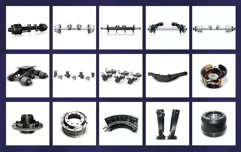
Axles

Split-axle

If you aren’t sure how to make split axles, you’re not alone. The process can be very difficult, and the parts can get mixed up. The key is to know how to create the proper alignment for your axles. Thankfully, there are some tools that can make this job a breeze.
Split axles have two components: a bolt head 30 that acts as a stop during relative pivotal movement. The axle assembly 16 is then pivotally mounted between the brackets and the frame. During pivotal movement, the bolt head 30 acts as a stop and prevents the axle from moving too far either way. This is done to maintain the pad 28 at a predetermined compression level. This allows the axle to perform a smooth and consistent drive.
Split axles are a common feature of modern vehicles. This type of suspension system provides greater traction, and it allows the left and right wheels to roll at different speeds. It also prolongs the life of tires, and increases traction.

Tandem

A tandem axle trailer is a great choice for hauling large loads. This style of trailer comes with more features and is more stable. These trailers are usually available in 16′, 18′, or 20′ lengths. They are also available with 8,500, or 10,000 GVW capacities. They are a great choice for hauling large loads on main highways.
Tandem axles are commonly used on trucks. Each axle features a drive mechanism, and are attached to the engine power unit. There are two types of tandem axles, one with a standard differential and the other with a power divider. Drivers may have trouble figuring out which axle is driving the truck at different times, so it is important to understand how each type of axle works.
While there are some common rules that apply to tandem axles, there are also some exceptions. In some cases, a single axle has a lower weight limit than a tandem axle, and the two axles must be at least 40 inches apart.

Drop-out

Drop-out axles are used to connect the dropouts of a bike frame. When using dropouts, make sure the distance between the axles is 110mm. Then use a clamp to squeeze the dropouts together. Make sure to measure both dropouts carefully, because a 1mm difference in the width can cause a lot of trouble.
The 9″ drop-out axle was produced from the late 1950s to 1986. They were made in trucks and cars, but not in motorcycles. To use this axle in a 1990 LTD CV, you will need to make several modifications to the mounting of the axle and connection to the drive line. You will also need to consider installing a parking brake. Moreover, this axle is not compatible with the Panther platform. In fact, the drop-out axle is available in several variations.
Drop-out axles are also known as single-speed. The lower part is called the semi-horizontal dropout, while the upper part is called the vertical dropout. This dropout includes an eyelet for mounting a fender or rack.
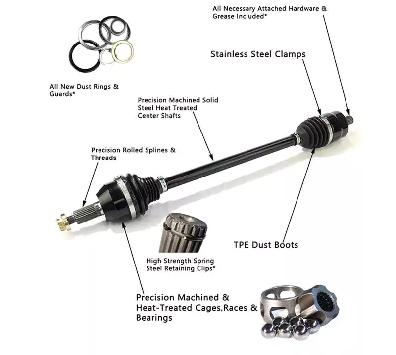
Axles

Czpt

The Czpt axle is a popular choice for a wide variety of vehicles. Initially used in heavy-duty pickup trucks, it was eventually adopted by all major automakers in the U.S., including Ford, Dodge, and Chrysler. It also became popular as a front differential on 4WD vehicles.
Czpt axles are easy to recognize, and the numbering system is consistent regardless of the vehicle model. The axle’s model number is found on the right lower web of the housing near the pinion yoke. It is also stamped on the axle tube. If you can’t find the axle model number, you can find it on Czpt’s website.
Czpt axles are also recognizable by their Bill of Materials (BOM) number. This is like a vehicle’s VIN number, and it identifies the axle’s gear ratio, model number, and component parts. A Czpt axle’s BOM number starts with 60 or 61.
The Czpt axle is the most common axle size in Jeeps. The Czpt 30 axle is the standard, and can be found on most Jeeps. The YJ version of this axle uses a reverse cut ring and pinion, while the TJ version does not. It is made from 5×4.5 inch bolts.

Universal joint

A universal joint is a component that connects two wheels to one another. This component is made to replace worn out or damaged parts on axles. They are also used to repair and replace brakes and drive shaft yokes. The universal joint can be purchased at an auto parts store or online. To replace a universal joint, you need to remove the axle shaft and the front brakes.
The universal joint is a flexible pivot point that transfers power between two shafts. In order to work properly, it must be flexible enough to compensate for changes in the driveline angle. These changes may be due to changing terrain. The universal joint is an important part of the driveline. It is used in both manual and automatic transmissions.
A universal joint should be serviced regularly to maintain its performance. If your universal joint squeaks while driving, it is a sign that it needs to be serviced. A lubricant can help extend the life of a u-joint.
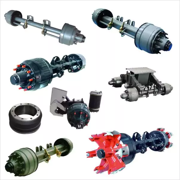
Axles

Spindle

Your vehicle’s axle consists of two main components: the hub and the spindle. The spindle rides on the hub, which can become damaged or lose its shape when it hits something. The spindle is also prone to wear from high mileage, and its threads can be damaged. If you suspect that your spindle needs to be replaced, there are several options available.
Axle spindles can be installed in one of three ways. The typical assembly includes bolted spindles on the ends of a tubular axle. The axle is then suspended by springs. Another type of mounting involves a torsion beam on the axle leg, which acts as a spring. It flexes and bends to provide the turning motion. The axle spindle can be a replacement part for your trailer, and there are towing supplies and professionals who can do it for you.
China 52761218 MC Oil Seal for Kubota Tractor Front Axle Shaft Rotary Seal agricultural mechanical seals     cv axle replacement costChina 52761218 MC Oil Seal for Kubota Tractor Front Axle Shaft Rotary Seal agricultural mechanical seals     cv axle replacement cost
editor by czh 2023-03-01

China supplier Cardan Shaft Tractor Pto Drive Power Take off Agricultural Transmission Manufacturing Heavy-Duty Farm Steering Industries Best Telescopic Cross Joints Shaft near me manufacturer

Product Description

Cardan Shaft Tractor Pto Drive Power Take off Agricultural Transmission Manufacturing Heavy-Duty Farm Steering Industries Best Telescopic Cross Joints Shaft

EPT Cardan Shafts, or even called u-joints, facilitate reliable torque transfer between spatially remote drive and output trains. Cardan shafts from CZPT offer suitable mechanical drive solutions in nearly all industrial sectors due to their versatile design and their high efficiency.

Our weight-optimised, energy-efficient, high-performance universal joint shafts are developed by using advanced methods and FEM calculations to provide optimal tube wall strengths and diameters for high torsion and bending resistance.

We use tempered steel and case-hardened steel for our u-joints. Calibrated precision steel tubes are used for particularly demanding solutions. All materials used fulfil the requirements for marine classification and rail vehicle applications. Reliable and continuous operation of our u-joints with a high torque capacity is therefore guaranteed. Our Cardan shafts are further characterised by low-maintenance components and low maintenance costs over the entire product life cycle.

How to Select a Worm Shaft and Gear For Your Project

You will learn about axial pitch PX and tooth parameters for a Worm Shaft 20 and Gear 22. Detailed information on these 2 components will help you select a suitable Worm Shaft. Read on to learn more….and get your hands on the most advanced gearbox ever created! Here are some tips for selecting a Worm Shaft and Gear for your project!…and a few things to keep in mind.
worm shaft

Gear 22

The tooth profile of Gear 22 on Worm Shaft 20 differs from that of a conventional gear. This is because the teeth of Gear 22 are concave, allowing for better interaction with the threads of the worm shaft 20. The worm’s lead angle causes the worm to self-lock, preventing reverse motion. However, this self-locking mechanism is not entirely dependable. Worm gears are used in numerous industrial applications, from elevators to fishing reels and automotive power steering.
The new gear is installed on a shaft that is secured in an oil seal. To install a new gear, you first need to remove the old gear. Next, you need to unscrew the 2 bolts that hold the gear onto the shaft. Next, you should remove the bearing carrier from the output shaft. Once the worm gear is removed, you need to unscrew the retaining ring. After that, install the bearing cones and the shaft spacer. Make sure that the shaft is tightened properly, but do not over-tighten the plug.
To prevent premature failures, use the right lubricant for the type of worm gear. A high viscosity oil is required for the sliding action of worm gears. In two-thirds of applications, lubricants were insufficient. If the worm is lightly loaded, a low-viscosity oil may be sufficient. Otherwise, a high-viscosity oil is necessary to keep the worm gears in good condition.
Another option is to vary the number of teeth around the gear 22 to reduce the output shaft’s speed. This can be done by setting a specific ratio (for example, 5 or 10 times the motor’s speed) and modifying the worm’s dedendum accordingly. This process will reduce the output shaft’s speed to the desired level. The worm’s dedendum should be adapted to the desired axial pitch.

Worm Shaft 20

When selecting a worm gear, consider the following things to consider. These are high-performance, low-noise gears. They are durable, low-temperature, and long-lasting. Worm gears are widely used in numerous industries and have numerous benefits. Listed below are just some of their benefits. Read on for more information. Worm gears can be difficult to maintain, but with proper maintenance, they can be very reliable.
The worm shaft is configured to be supported in a frame 24. The size of the frame 24 is determined by the center distance between the worm shaft 20 and the output shaft 16. The worm shaft and gear 22 may not come in contact or interfere with 1 another if they are not configured properly. For these reasons, proper assembly is essential. However, if the worm shaft 20 is not properly installed, the assembly will not function.
Another important consideration is the worm material. Some worm gears have brass wheels, which may cause corrosion in the worm. In addition, sulfur-phosphorous EP gear oil activates on the brass wheel. These materials can cause significant loss of load surface. Worm gears should be installed with high-quality lubricant to prevent these problems. There is also a need to choose a material that is high-viscosity and has low friction.
Speed reducers can include many different worm shafts, and each speed reducer will require different ratios. In this case, the speed reducer manufacturer can provide different worm shafts with different thread patterns. The different thread patterns will correspond to different gear ratios. Regardless of the gear ratio, each worm shaft is manufactured from a blank with the desired thread. It will not be difficult to find 1 that fits your needs.
worm shaft

Gear 22’s axial pitch PX

The axial pitch of a worm gear is calculated by using the nominal center distance and the Addendum Factor, a constant. The Center Distance is the distance from the center of the gear to the worm wheel. The worm wheel pitch is also called the worm pitch. Both the dimension and the pitch diameter are taken into consideration when calculating the axial pitch PX for a Gear 22.
The axial pitch, or lead angle, of a worm gear determines how effective it is. The higher the lead angle, the less efficient the gear. Lead angles are directly related to the worm gear’s load capacity. In particular, the angle of the lead is proportional to the length of the stress area on the worm wheel teeth. A worm gear’s load capacity is directly proportional to the amount of root bending stress introduced by cantilever action. A worm with a lead angle of g is almost identical to a helical gear with a helix angle of 90 deg.
In the present invention, an improved method of manufacturing worm shafts is described. The method entails determining the desired axial pitch PX for each reduction ratio and frame size. The axial pitch is established by a method of manufacturing a worm shaft that has a thread that corresponds to the desired gear ratio. A gear is a rotating assembly of parts that are made up of teeth and a worm.
In addition to the axial pitch, a worm gear’s shaft can also be made from different materials. The material used for the gear’s worms is an important consideration in its selection. Worm gears are usually made of steel, which is stronger and corrosion-resistant than other materials. They also require lubrication and may have ground teeth to reduce friction. In addition, worm gears are often quieter than other gears.

Gear 22’s tooth parameters

A study of Gear 22’s tooth parameters revealed that the worm shaft’s deflection depends on various factors. The parameters of the worm gear were varied to account for the worm gear size, pressure angle, and size factor. In addition, the number of worm threads was changed. These parameters are varied based on the ISO/TS 14521 reference gear. This study validates the developed numerical calculation model using experimental results from Lutz and FEM calculations of worm gear shafts.
Using the results from the Lutz test, we can obtain the deflection of the worm shaft using the calculation method of ISO/TS 14521 and DIN 3996. The calculation of the bending diameter of a worm shaft according to the formulas given in AGMA 6022 and DIN 3996 show a good correlation with test results. However, the calculation of the worm shaft using the root diameter of the worm uses a different parameter to calculate the equivalent bending diameter.
The bending stiffness of a worm shaft is calculated through a finite element model (FEM). Using a FEM simulation, the deflection of a worm shaft can be calculated from its toothing parameters. The deflection can be considered for a complete gearbox system as stiffness of the worm toothing is considered. And finally, based on this study, a correction factor is developed.
For an ideal worm gear, the number of thread starts is proportional to the size of the worm. The worm’s diameter and toothing factor are calculated from Equation 9, which is a formula for the worm gear’s root inertia. The distance between the main axes and the worm shaft is determined by Equation 14.
worm shaft

Gear 22’s deflection

To study the effect of toothing parameters on the deflection of a worm shaft, we used a finite element method. The parameters considered are tooth height, pressure angle, size factor, and number of worm threads. Each of these parameters has a different influence on worm shaft bending. Table 1 shows the parameter variations for a reference gear (Gear 22) and a different toothing model. The worm gear size and number of threads determine the deflection of the worm shaft.
The calculation method of ISO/TS 14521 is based on the boundary conditions of the Lutz test setup. This method calculates the deflection of the worm shaft using the finite element method. The experimentally measured shafts were compared to the simulation results. The test results and the correction factor were compared to verify that the calculated deflection is comparable to the measured deflection.
The FEM analysis indicates the effect of tooth parameters on worm shaft bending. Gear 22’s deflection on Worm Shaft can be explained by the ratio of tooth force to mass. The ratio of worm tooth force to mass determines the torque. The ratio between the 2 parameters is the rotational speed. The ratio of worm gear tooth forces to worm shaft mass determines the deflection of worm gears. The deflection of a worm gear has an impact on worm shaft bending capacity, efficiency, and NVH. The continuous development of power density has been achieved through advancements in bronze materials, lubricants, and manufacturing quality.
The main axes of moment of inertia are indicated with the letters A-N. The three-dimensional graphs are identical for the seven-threaded and one-threaded worms. The diagrams also show the axial profiles of each gear. In addition, the main axes of moment of inertia are indicated by a white cross.

China supplier Cardan Shaft Tractor Pto Drive Power Take off Agricultural Transmission Manufacturing Heavy-Duty Farm Steering Industries Best Telescopic Cross Joints Shaft   near me manufacturer China supplier Cardan Shaft Tractor Pto Drive Power Take off Agricultural Transmission Manufacturing Heavy-Duty Farm Steering Industries Best Telescopic Cross Joints Shaft   near me manufacturer